BACKBOARD YOKE FRAME/HINGE WELDMENTS
MUST BE CENTERED LEFT-TO-RIGHT
111214
16
6
15 913
1
17
5
ON GLASS BACKBOARD FRAME
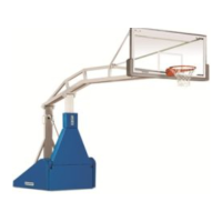
Detail
"C"
7. Lay backboard yoke frame (#5)
on the top side of the backstop
horizontal extension assembly,
positioning upper ends of the
yoke into the hinges in the upper
corners of the backboard
assembled in Step No. 6. Secure
in place with two (2) 1/2" x 3" lg.
hex head cap screws (#9), 1/2"
hex nuts (#13) and 1/2"
lockwashers (#15). Use 1/2"
flatwashers (#17) as spacers on
either side of backboard yoke
frame (#2) (see Detail “C”).
Center the two hinge weldments
(#6) on the frame of the
backboard and tighten all bolts
securely.
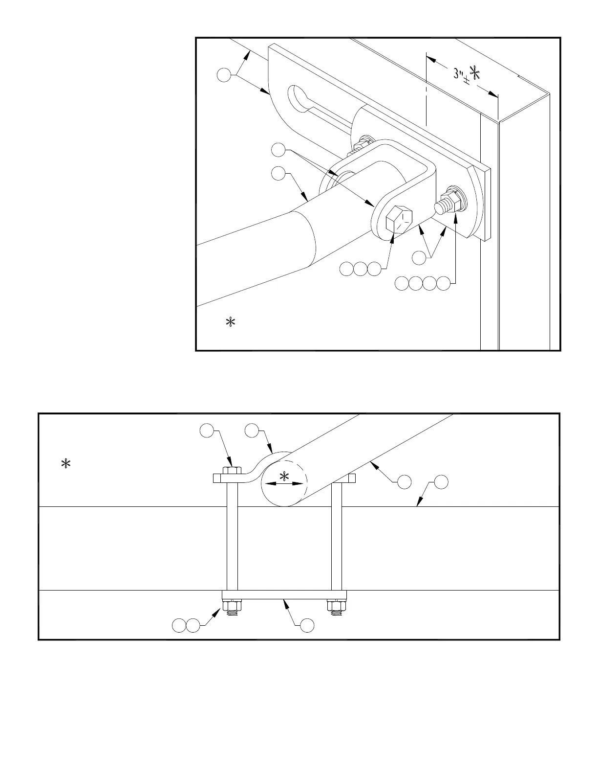
8. Attach lower end of backboard yoke frame (#5) to the top tube of the horizontal extension assembly (see Detail “D”) using two
(2) half clamps (#8), mounting plate (#7), and four (4) 3/8" x 5-1/2" hex head cap screws (#10), 3/8" hex nuts (#12) and 3/8"
lockwashers (#14). Snug bolts only at this time.
4
14
7
12
ADJUST BACKBOARD YOKE FRAME
FRONT-TO-BACK TO PLUMB
Detail "D"
FACE OF BACKBOARD
10 8
5
8