ASSEMBLY
INSTRUCTIONS
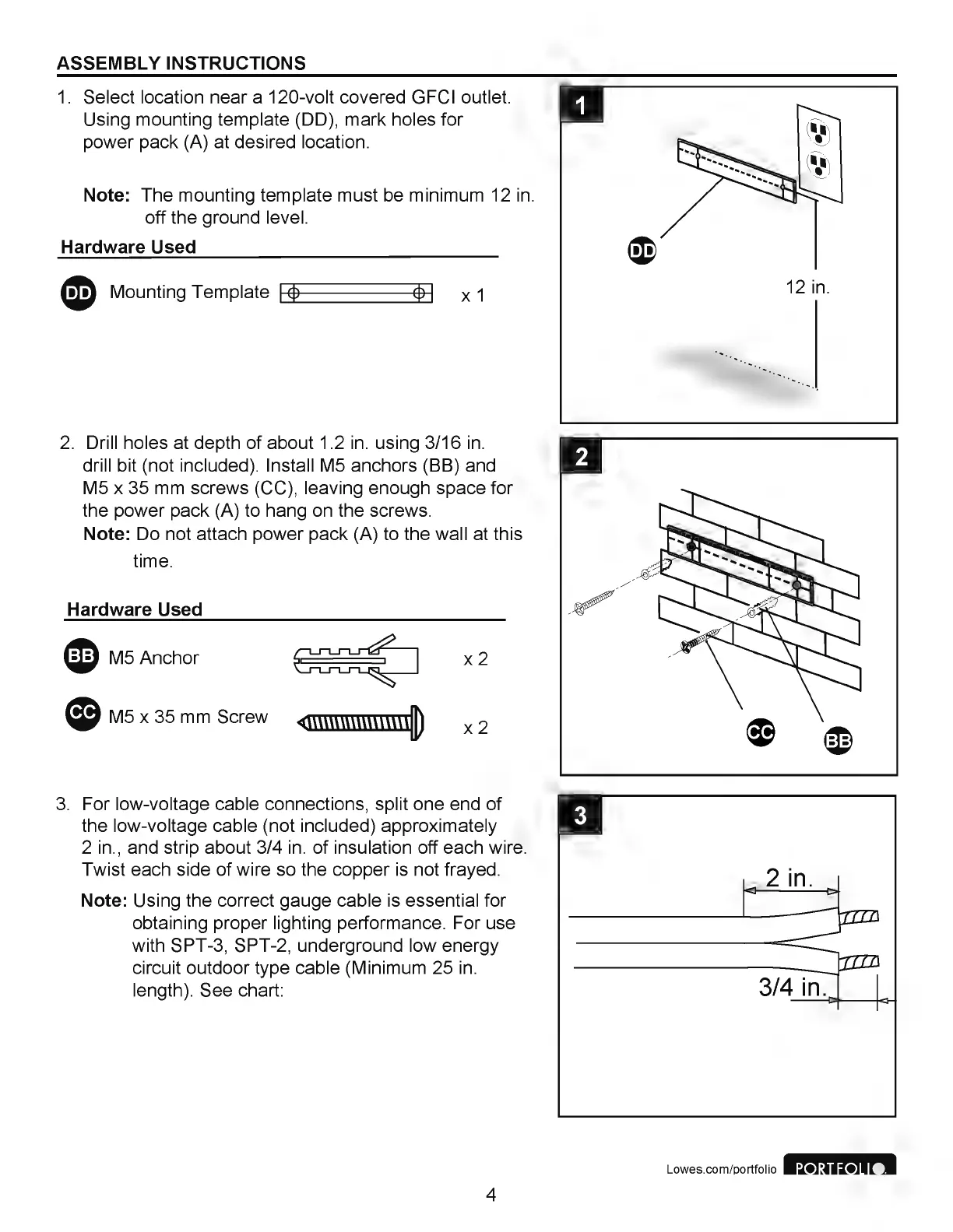
1.
Select location near a 120-volt covered GFCI outlet.
Using mounting template
(DD), mark holes for
power pack (A) at desired location.
Note: The mounting template must be minimum 12
in.
off the ground level.
Hardware Used
~
Mounting Template ll-f$tt--------ti$ft-ll x 1
2.
Drill holes at depth
of
about 1.2
in.
using 3/16
in.
drill bit (not included). Install M5 anchors (BB) and
M5 x 35 mm screws (CC), leaving enough space for
the power pack (A) to hang on the screws.
Note: Do not attach power pack (A) to the wall at this
time.
Hardware Used
ID
M5 Anchor
~
x2
0 M5 x 35 mm Screw (\\\\\\"\\\\\\\\1\ID
x2
3.
For low-voltage cable connections, split one end
of
the low-voltage cable (not included) approximately
2
in.,
and strip about 3/4
in.
of
insulation off each wire.
Twist each side
of
wire so the copper
is
not frayed.
Note: Using the correct gauge cable is essential for
obtaining proper lighting performance. For use
with SPT-3, SPT-2, underground low energy
circuit outdoor type cable (Minimum 25
in.
length). See chart:
4
12
in.
2
in.
Lowes.
co
m/po rtfol
io
 Loading...