INSTALLATION MANUAL: PAD100-PSSA / PSDA PULL STATION (SINGLE & DUAL ACTION)
Document 5406320-A 02/16
Potter Electric Signal Company, LLC • St. Louis, MO • Phone: (800) 325-3936 • www.pottersignal.com
PAGE 2 OF 3
Before connecting a device to the SLC loop, take the following precautions to prevent potential damage to the SLC or device.
• Power to the SLC is removed.
• Field wiring on module is correctly installed.
• Field wiring has no open or short circuits.
3. Technical Specications
Operating Voltage 24.0V
Max SLC Standby Current 200 μ A
Max SLC Alarm Current 200 μ A
Temperature Range
32 to 120 F (0 to 49 C)
Relative Humidity Range 0 to 93% (non-condensing)
Dimensions 4.75" L x 3.25" W x 1.75" D
Mounting Options Single gang box or Potter P32-BB/DBB
Shipping Weight APS-SA –1.22 lbs
APS-DA – 1.46 lbs
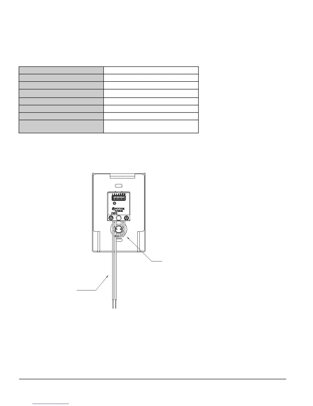
4. Wiring Diagrams
The wiring diagram shown below illustrates how to wire a PAD100-PSSA / PSDA module. Additionally, two drawings are provided
showing the front view of each module.
Figure 3. Example of Back View and Wiring a PAD100-PSSA / PSDA
FACTORY WIRED CONTACTS
FROM FACP OR
PREVIOUS DEVICE
TO NEXT DEVICE
 Loading...