PAD300-DD (In-Duct/Plenum Mount Applications)
Contents
A. Introduction E. Addressing
B. Specications
F. Testing
C. Installation
G. Cleaning
D. Locking Feature H. Warranty
PAD300-DD
Operating Voltage
24 VDC
Standby Current (*)
300 A
Alarm Indicator Current
1.4 mA
Alarm Set Point
2.5%/
Installation Temp Range
32F to 120F
Operating Humidity Range
0% - 93% (Non-condensing)
Air Velocity (In-duct)
300 to 3,000 fpm
Dimension
Φ 3.93 in
Weight
3.20 oz
Height
1.42 in
*Standby current is the current the device consumes when the device
is in a non-activated condition and where no communication current
is transmitted to the re alarm control panel.
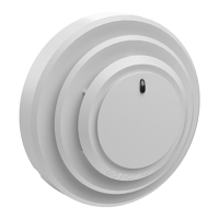
e PAD300-DD is an intelligent addressable photoelectric duct
smoke detector designed and built to meet both UL268A and NFPA
regulations. It is intended for indoor use within a duct (In-duct) or
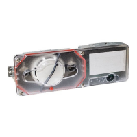
in plenums. It can also be mounted in a PAD300-DUCT or PAD300-
DUCTR with sampling tubes extending into a duct. Maximum air
velocity for In-duct/plenum applications is 3,000 fpm. Maximum air
velocity for PAD300-DUCT and PAD300-DUCTR is 4,000 fpm. To
minimize false alarms, avoid placing in areas where excessive dust,
humidity, air movement, or extreme temperature is present.
is manual only covers the installation guidelines for In-duct/
plenum applications. For standard external mount duct applications,
please refer to the installation manual for PAD300-DUCT and
PAD300-DUCTR.
Each detector includes one (1) LED to indicate the device status.
e LED ashes momentarily in normal conditions and ashes
at a fast rate when activated. e LED can be turned o using the
programming soware.
e PAD300-DD communicates on a proprietary protocol to the
addressable re alarm control panel. It must be connected to either
the IPA series, AFC series, or ARC re alarm control panel for proper
operation. For detector sensitivity settings and supervision, please
refer to the panel installation instructions.
Refer to the company website for the latest revision of this manual.
B. Specications
A. Introduction
Installation must meet the requirements of the Authority Having
Jurisdiction (AHJ). It is recommended to follow guidelines as
described in NFPA 72 and NFPA 90A.
1. Before connecting a device to the SLC loop, take the following
precautions to prevent potential damage to the SLC or device.
• Use only the PAD300 series bases PAD300-4DB and
PAD300-6DB (supplied separately).
• Conrm the eld wiring on device is correctly installed on
the base. Refer to the base manual.
• Enable the locking feature if needed. Refer to section D for
details of the locking feature.
2. Set the desired address using the DIP switch located on back of
the sensor. See section E for addressing instructions.
3. Plug detector into base and turn clockwise to secure in place.
C. Installation
KEEP DUST COVER ON DETECTOR DURING
CONSTRUCTION. REMOVE DUST COVER TO ALLOW THE
DETECTOR TO DETECT SMOKE.
DETECTORS ARE NOT TO BE USED WITH DETECTOR
GUARDS UNLESS THE COMBINATION HAS BEEN EVALUATED
AND FOUND SUITABLE FOR THAT PURPOSE.
1. To minimize the impact of air turbulence and stratication
on performance, detector should be located as far as possible
downstream from any obstruction. Conrmation of velocity
within specications is required.
2. Identify a code compliant location (supply or return side, or
both) for the installation of the duct unit that will permit easy
access for inspection and serviceability.
3. When mounted in plenum space or duct handling space, it is
critical that the detector is situated such that the airstream ows
through the opening of the head. See below.
Airow
e device includes a tamperproof feature that locks the detector and
does not allow removal without the use of a tool.
D. Locking Feature
Break o tab (gray area in
image). e locking feature
is enabled.
Insert a small
screwdriver into slot
to remove detector.
1609 Park 370 Pl, Hazelwood, MO 63042
www.pottersignal.com