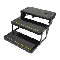
This document provides a troubleshooting flowchart for an Electric Step, likely used in recreational vehicles (RVs) or other vehicles to assist with entry and exit. The flowchart guides users through a series of diagnostic steps to identify and resolve common issues that prevent the step from operating correctly.
Function Description:
The electric step is designed to extend when the vehicle door opens and retract when the door closes, providing a convenient and safe way to enter and exit the vehicle. Its operation is controlled by a combination of electrical signals, switches, and a motor-driven mechanism. The troubleshooting process aims to pinpoint failures in this system, which can range from power supply issues to faulty switches, wiring, or mechanical components.
Important Technical Specifications (Inferred from Flowchart):
- Battery Voltage: The system operates on a 12V battery supply. Critical checks involve verifying that the battery provides at least 12V and that specific wires (RED, YELLOW, WHITE) receive appropriate voltage levels (battery voltage or 0V) at different stages of operation.
- Fuses: The system incorporates fuses for protection. A 20 amp fuse is mentioned for the RED wire circuit, and a 6 amp fuse for the YELLOW wire circuit, and a 5 amp fuse for the WHITE wire circuit, indicating specific current requirements and protection levels for different parts of the system.
- Wiring: The system uses a 4-wire plug connection at the step, and a 2-wire connector to the motor. Specific wires mentioned are RED, YELLOW, WHITE, and BROWN, each likely serving a distinct function in the control and power distribution.
- Switches: Key switches involved in the operation include an "Override Switch" and a "door switch." The override switch likely allows manual control or disables automatic operation, while the door switch detects the open/closed state of the vehicle door.
- Components: The system includes a motor, a main gearbox, and a control module, which are critical for the mechanical movement and electronic control of the step.
Usage Features (Inferred from Troubleshooting Steps):
- Automatic Operation: The step is designed to operate automatically based on the door's state (open/closed).
- Ignition Dependency: The YELLOW wire circuit's voltage is checked with the ignition in the "RUN" and "OFF" positions, suggesting that the step's operation or certain control functions might be linked to the vehicle's ignition status.
- Override Functionality: The presence of an "Override Switch" indicates a feature to temporarily disable or manually control the step's automatic function. This could be useful for maintenance, cleaning, or specific parking situations.
- Safety Features: The fuses are a key safety feature, protecting the electrical circuits from overcurrents that could damage components or cause hazards.
Maintenance Features (Inferred from Troubleshooting Steps):
- Visual Inspection: The flowchart emphasizes checking ground wires for cleanliness and tightness, and inspecting connections for poor contact or breaks. This highlights the importance of regular visual inspections of wiring and connections.
- Voltage Measurement: A multimeter is an essential tool for troubleshooting, used to measure battery voltage and voltage on specific wires (RED, YELLOW, WHITE, BROWN) at various points in the circuit. This allows for precise diagnosis of electrical issues.
- Continuity/Resistance Checks: The door switch is checked with an Ohmmeter, indicating that continuity or resistance measurements are part of the diagnostic process for certain components.
- Component Replacement: The flowchart directs users to replace specific components such as the door switch, defective control module, defective motor, or gearbox/linkage if they are identified as faulty. This suggests that these components are designed to be replaceable.
- Mechanical Inspection: Removing the motor from the main gearbox to check for internal damage and inspecting for broken or damaged gears points to the need for mechanical inspection and repair/replacement of mechanical drive components.
- Online Resources: The repeated instruction to "Check www.lci1.com for the latest information" indicates that the manufacturer provides online support and updated information, which is a valuable maintenance resource.
The troubleshooting process is structured logically, starting with basic power checks and progressively moving to more specific component and circuit diagnostics. It covers a comprehensive range of potential failure points, from the power source to the final mechanical actuation, making it a practical guide for diagnosing and repairing an inoperative electric step.