Installing the Laser Batteries
WARNING: RISK OF PERSONAL INJURY. Always disconnect the tool from the power outlet
before making any adjustment, installing or changing the accessories.
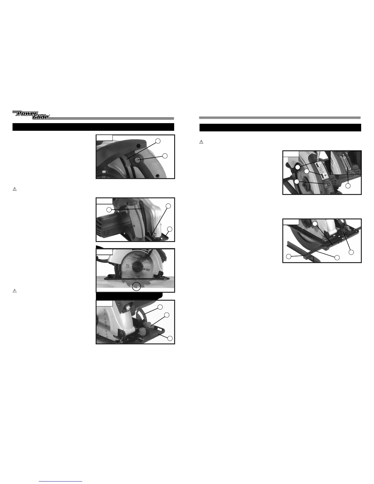
1. (SEE FIGURE 1) Turn the On/Off rocker
switch (1) to the off "O" position.
2. Remove the battery cover Phillips head
screw (2). Lift and remove the battery
cover (3), rear (screw end) first.
3. Insert new "AAA" size alkaline type
batteries (4), paying attention to proper
polarity (+ / -) installation direction.
4. Replace the battery cover and screw.
Installing the Rip Fence
For repetitive cuts or when ripping long
material use the rip fence for accuracy.
1. (SEE FIGURE 2) Slide the fence (1) into the
slots of base (2). Adjust to desired position
shown on scale (3) and secure with
adjustment knob (4).
NOTE: Check blade alignment before
cutting. The rip fence scale (3) will provide
quick set-up and satisfactory accuracy for
most applications. For precision cutting,
check alignment with a separate
measuring device.
9
6
FUNCTIONAL DESCRIPTION
On/Off Switch
1. (SEE FIGURE 5) To start the saw, depress
the safety button (1) and pull the On-Off
trigger switch (2).
2. To stop the saw, release the trigger switch.
Depth of Cut Adjustment
By setting the proper blade depth, you can
minimize saw kickback and improve
cutting efficiency.
CAUTION: Always tighten the depth adjust-
ment lever securely before operating saw.
1. (SEE FIGURE 6) Rotate depth adjustment
lever (1) upwards to loosen base plate.
2. Slide base plate (2) up to increase depth of
cut or downwards to reduce depth. Use
depth scale (3) to set approximate
cutting depth.
3. With base plate in desire position, rotate
depth adjustment lever downwards to
secure base plate.
4. (SEE FIGURE 7) Check depth of cut to the
thickness of the workpiece. Less than a full
tooth of the blade teeth should be visible
below workpiece.
Bevel Cut Adjustment
CAUTION: Always tighten the bevel adjust-
ment knob securely before operating saw.
1. (SEE FIGURE 8) Loosen the bevel adjust-
ment knob (1) at the front of the saw.
2. Tilt the base (2) to the desired angle shown
on the bevel scale (3).
3. Tighten the bevel adjustment knob to
secure the base.
ASSEMBLY
Figure 1
Figure 2
1
1
2
1
1
2
3
2
3
3
4
4
2
Figure 5
Figure 6
Figure 7
1
2
3
Figure 8



 To Next Page