PX-S10 / PX-S20
Owners and
Installation Manual
. Main features
1. IP68 waterproof and aluminum housing.
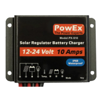
2. Automatic identification of 12V/24V system voltage.
3. LED digital display.
4. External temperature sensor for ambient temperature compensation.
5. Over charging protection, over discharging protection, over load, short circuit
protection, reverse polarity protection.
6.
. Installation and wiring
1. Installation of controller should be stable and dimensions are as follows:
Overall dimension: 82×58×20mm (PX-S10) 82×100×20mm (PX-S20)
Installation dimension: 43×75mm (PX-S10) 86×75mm (PX-S20)
Installation hole diameter: 3.5mm
2. The controller can be used for 12V or 24V battery banks. Once the battery is
connected it will automatically detect whether it’s connect to a 12V or 24V battery
bank. For 12 Volt battery banks the digital display will show “0.” when the battery is
first connected. For 24V battery banks the digital display will show “1.”. So please
check to ensure it’s detected the correct battery bank size.
3. The controller is designed to share the positive (+) pole. Please connect the
positives of storage battery, solar input and the load (if being used) to the red
(positive +) wire of the controller
4. Connect Battery Black negative (-) wire to the Battery. (Make sure it auto detects
the correct battery voltage) – We also recommend using adequate size fuse to suit
your application.
5. Connect Solar Black negative (-) wire to the Battery: We recommend using
adequate size fuse to suit your application.
6. Connecting pole ‘-’o f the load: connect the load wire to the load output end of
controller. Current should not exceed the rated current of controller. We
recommend using adequate size fuse to suit your application.
Wiring diagram is as follows: Please use adequate size wiring/ fuses.
Please install the controller in a ventilated area and close to the battery to ensure the
battery compensation is effective .
. Status indications
There is voltage on battery panel
No voltage on battery panel
Over voltage on Solar input
Battery is deeply discharged
Short circuit protection mode
. Modes and Settings
The PX series controllers have five working modes.
1. Purely light-operated (0): When there is no sunlight, the load output will turn on.
When there is sunlight the load output will turn off.
2. Light-operated + time-controlled (1~4.): Starting process is same as above
however the load will automatically turn off after the time period selected. Set time
will be 1 to 14 hours.
3. Manual mode (5.): Under this mode, users can control the load-on and load-off by a
short press of the key/button. This mode is suitable to occasions in need of special
loads or for debugging.
4. Debug mode (6.): It is used for system debug. If there is light signal, load will be
closed. If there is no light signal, load will be opened. It is convenient for checking
the correctness of the system during installation and debugging.
5. Long-term On mode (7.): If being powered on, the load will be under the output
status all the time. This mode is suitable for loads in need of 24-hour power supply.
Light-operated +
time-controlled for 9
hours
Light-operated +
time-controlled for 1 hour
Light-operated +
time-controlled for 10
hours
Light-operated +
time-controlled for 2 hours
Light-operated +
time-controlled for 11
hours
Light-operated +
time-controlled for 3 hours
Light-operated +
time-controlled for 12
hours
Light-operated +
time-controlled for 4 hours
Light-operated +
time-controlled for 13
hour
Light-operated +
time-controlled for 5 hours
Light-operated +
time-controlled for 14
hours
Light-operated +
time-controlled for 6 hours
Manual mode
(Key/button turns load
on/off)
Light-operated +
time-controlled for 7 hours
Light-operated +
time-controlled for 8 hours
. How to change settings
Press the mode key/button for more than 3s until the Display starts flashing. Keep
pressing the key/button until it shows the desired mode/setting. Once you have the
correct mode/setting selected, wait for more than 3 seconds and settings will be saved.
. Safety suggestions
1. Please do not immerse the controller into corrosive liquid. Otherwise, controller
may be damaged and harmful gas may be generated.
2. When connecting 24V system, terminal voltage of battery panel may surpass the
human body safety voltage. If operations are needed, insulating tools should be
used and hands must be dry.
3. If storage battery is connected in reverse, the controller would not be damaged.
However, there may be output of negative voltage at the load end which may
damage anything connected to your load
4. Storage battery may generate combustible gas and therefore should be far away
from sparks.
5. Please make sure that children are far away from the storage battery and the
controller.
6. Please follow the safety suggestions given by the battery manufacturer.
. Instructions for parameters
PX-S10 - 55VDC Max. 150W(12V) – 300W(24V)
PX-S20 - 55VDC Max. 300W(12V) – 600W(24V)
Equalising charging
voltage
Return voltage during
charging
Return voltage for
over-discharging
Overload and short
circuit protection
1.25 times of rated current: 30s;
1.5 times of rated current: 5s overload protection
activity;
≥3 times of rated current: short circuit protection
140g (PX-S10) 300g (PX-S20)
82×58×20mm (PX-S10) 82×100×20mm
(PX-S20)
Specifications subject to change without notice : 08/15 Rev 1.1