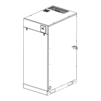
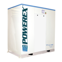
Scroll Enclosure Air Compressor
Please read and save these instructions. Read carefully before attempting to assemble, install, operate or maintain the product
described. Protect yourself and others by observing all safety information. Failure to comply with instructions could result in
personal injury and/or property damage! Retain instructions for future reference.
Powerex • 150 Production Drive • Harrison, OH 45030 • USA
1-888-769-7979
IN558804AV 6/12
Specifi cations
Product SED, SET, SEQ, SEH and SEO Series
Performance
Specifi cations
See Page 2
Lubrication Grease-fi lled Bearings / Dry Scroll
Operating Voltages 3Ø 208-230/460 Volts, 60 Hz
Compression Cycle Scroll
Motor Overload
Protection
IEC Motor Overload Relay
Pressure Settings
Working Pressure
Cut-In: 94 psig Cut-Out: 116 psig
Cut-In: 116 psig Cut-Out: 145 psig
(High Pressure Unit)
Overpressure
Protection
Safety Valve Factory Set and Sealed
Outlet Air
Connections
See Page 2
Minimum
Recommended Tank
Sizes
See Page 5, Chart 2
Unit Isolation Standard All Units
Drive 3V Belt
Control Panel UL508A Listed for medical units
Description
Powerex Scroll Enclosure Air Compressors are designed to
supply continuous oil-free air by using the most advanced
scroll technology. These turn-key packages are extremely
quiet and offer electronic control that will reduce electrical
power consumption.
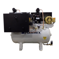
The Powerex Oilless Rotary Scroll Air Compressor has
advanced scroll compressor technology through the
development of a completely oilless unit. The Powerex Scroll
Compressor offers a dynamically balanced air end which
insures vibration-free operation. The rotary design permits a
continuous 100% duty cycle. No oil separation, oil fi ltration,
or inlet valves are required on the Powerex Scroll unit. The
compressor is virtually maintenance free.
The Powerex Oilless Rotary Scroll Air Compressor is based on
the theory of scroll compression. A scroll is a free standing,
intricate spiral bounded on one side by a solid, fl at plane or
base. A scroll set, the basic compression element of a scroll
compressor, is made up of two identical spirals which form
right and left hand parts. One of these scroll components
is indexed or phased 180° with respect to the other so the
scrolls can mesh. Crescent-shaped gas pockets are formed
and bounded by the spirals and the base plate of both
scrolls. As the moving scroll is orbited around the fi xed scroll,
the pockets formed by the meshed scrolls follow the spiral
toward the center and diminish in size. The moving scroll is
prevented from rotating during this process so the 180° phase
relationship of the scrolls is maintained. The compressor’s
inlet is at the outer boundary of the scrolls. The entering
gas is trapped in two completely opposite gas pockets and
compressed as the pockets move toward the center. The
compressed gas is discharged through the outlet at the center
of the fi xed scroll so no valves are needed.