INSTALLATION Cont’d
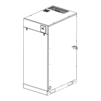
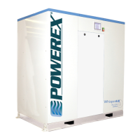
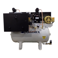
10HP - 20HP Scroll Enclosure Air Compressors
WIRING
Pg 5
All electrical hook-ups must be performed by a qualified
electrician. Installations must be in accordance with local and
national electrical codes.
1. A service disconnect and fuses or a circuit breaker must be
installed to supply electric power to this compressor. Make
sure the circuit is sized to handle the full operating load as
shown in the table on the wiring diagram. Branch circuit
protection must be provided as specified in National Electric
Code, Chapter 2, “Wiring Design and Protection,” Article
210, using the applicable article “For Motors and Motor
Controllers.” (Article 430)
2. Remove the front panel to access the wiring area.
3. Using the appropriate strain relief and cable management
techniques, connect the power cable to the power junction
block and the ground wire to the ground bar.
Consult your NEC and local codes for wire size.
All wiring and electrical connections must be performed by
a qualified electrician. Installations must be in accordance
with local and national codes.
Overheating, short circuiting
and fire damage will result from
inadequate wiring.
Wiring must be installed in accordance with National Electric
Code and local codes and standards that have been set up
covering electrical apparatus and wiring. Consult the codes
and standards and observe local ordinances. Be certain that
adequate wire sizes are used, and that:
1. Service is of adequate ampere rating.
2. The supply line has the same electrical characteristics
(voltage cycles and phase) as the motor.
3. Ensure the line wire is the proper size and that no other
equipment is operated from the same line. The chart
gives the recommended wire sizes for horsepower of
motor provided.
Recommended wire sizes may be larger than the minimum
set up by local ordinances. If so, use the large size wire to
prevent excessive line voltage drop.
MINIMUM WIRE SIZE
USE 75
O
C COPPER WIRE
Single
Phase
Three Phase
230V 208/230V 460/575V
3 10 AWG 14 AWG 14 AWG
5 8 AWG 12 AWG 14 AWG
7.5 8 AWG 10 AWG 12 AWG
10 N/A 8 AWG 12 AWG
15 N/A 6 AWG 10 AWG
25 N/A 3 AWG 8 AWG
HP
The additional wire cost is very small compared with the cost
of repairing or replacing a motor electrically “starved” by the
use of supply wires which are too small.
Improperly grounded electrical components
are shock hazards. Make sure all the compo-
nents are properly grounded to prevent death
or serious injury.
GROUNDING
This product must be grounded. Grounding reduces the risk
of electrical shock by providing an escape wire for the
electrical current if short circuit occurs.
PIPING
Never use plastic (PVC) pipe for compressed air. Serious
injury or death could result.
Any tube, pipe or hose connected to the unit must be able to
withstand the temperature generated and retain the pressure.
All pressurized components of the air system must have a
pressure rating higher than or equal to the ASME safety valve
setting. Incorrect selection and installation of any tube, pipe
or hose could result in bursting and injury.
MINIMUM PIPE SIZE FOR
COMPRESSED AIR LINE
Length of Piping System
CFM
25’
50’ 100’ 250’
10 1/2” 1/2” 1/2” 3/4”
20 3/4 3/4 3/4 1
40 3/4 1 1 1
60 3/4 1 1 1
100 1 1 1 1- 1/4
GENERAL FAULT DRY CONTACT CONNECTION
1. Turn the compressor off and lockout the power to the
compressor per OSHA standards.
2. Remove the door panel from the scroll cabinet to access
the operating panel.
3. Output wires should be connected between terminals 10
and 11. The dry contacts are normally closed; when there is a
fault or loss of power to the system, the contacts open. The
contact rating is as follows: 240 VAC/2A or 30VDC/2A,
maximum.
4. For larger load devices such as a horn or emergency light,
a relay should be used.
5. The signal wires should be between 24 and 12 AWG and
run through the grommet provided beneath the terminal
blocks.
6. Replace the door panel to the scroll compressor cabinet.
7. Return the power to the compressor system.
 Loading...