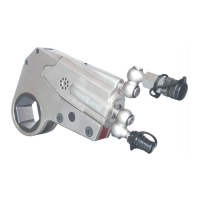
The PXD Series Low Profile Hydraulic Torque Wrenches are power tools designed for the precise installation and removal of large bolts, particularly in applications with minimal wrench clearance. These wrenches are suitable for demanding environments such as windmills, offshore platforms, power plants, and steel erection sites, where accurate high torque is critical during bolt tightening and for managing maximum torque during bolt failure.
Function Description
The PXD Series Hydraulic Torque Wrenches operate by connecting to a hydraulic power pack, which can be driven pneumatically or electrically. The tool utilizes high-pressure fluid to generate significant force, accuracy, and efficiency in bolting tasks. The power stroke of the piston assembly consistently turns the ratchet hex towards the shroud, facilitating both tightening and loosening operations depending on the tool's orientation relative to the nut.
Important Technical Specifications
The PXD Series offers a range of models (PXD-1, PXD-2, PXD-4, PXD-8, PXD-16, PXD-32, PXD-45), each with varying torque capacities and dimensions.
General Specifications:
- Maximum Pressure: 10,000 psi (681 bars)
- Output Accuracy: +/-3%
- Repeatability: 100%
- Duty Cycle: 100%
- Corrosion Protection: Standard
- Hydraulic Hose: Twin Line Hydraulic hose rated for 10,000 psi (681 bars) pressure with a safety rating of 4:1.
- Couplers: High Pressure Quick Releasing Couplers with spring-loaded retaining rings and safety rings.
Model-Specific Torque and Weight (Kg-m / ft/lbs):
- PXD-1:
- Min Torque: 6 (45)
- Max Torque: 77 (560)
- Cylinder Weight: 0.50 (1)
- Link Weight: 0.50 (1)
- PXD-2:
- Min Torque: 26 (192)
- Max Torque: 260 (1928)
- Cylinder Weight: 1.59 (3.50)
- Link Weight: 1.09 (2.40)
- PXD-4:
- Min Torque: 54 (395)
- Max Torque: 540 (3950)
- Cylinder Weight: 2.73 (6.00)
- Link Weight: 2.45 (5.40)
- PXD-8:
- Min Torque: 115 (830)
- Max Torque: 1192 (8630)
- Cylinder Weight: 5.32 (11.70)
- Link Weight: 5.41 (11.90)
- PXD-16:
- Min Torque: 245 (1560)
- Max Torque: 2293 (16600)
- Cylinder Weight: 7.27 (16.00)
- Link Weight: 5.41 (11.90)
- PXD-32:
- Min Torque: 445 (3220)
- Max Torque: 4924 (35650)
- Cylinder Weight: 11.82 (26.00)
- Link Weight: 9.55 (21.00)
- PXD-45:
- Min Torque: 658 (4865)
- Max Torque: 6410 (47380)
- Cylinder Weight: 13.70 (30.20)
- Link Weight: 13.18 (29.00)
Model-Specific Dimensions (Length x Height x Width x Radius in mm / inch):
- PXD-1: 111.00 (4.37) x 82.60 (3.25) x 19.80 (0.78) x 5.80 (0.23)
- PXD-2: 167.00 (6.57) x 103.00 (4.05) x 38.00 (1.49) x 9.30 (0.36)
- PXD-4: 203.20 (8.00) x 144.00 (5.66) x 50.70 (1.99) x 11.85 (0.46)
- PXD-8: 253.00 (9.96) x 179.50 (7.06) x 59.50 (2.34) x 13.90 (0.54)
- PXD-16: 330.00 (13.00) x 193.80 (7.63) x 65.00 (2.56) x 16.80 (0.66)
- PXD-32: 390.00 (15.35) x 278.00 (10.94) x 84.00 (3.30) x 23.75 (0.94)
- PXD-45: 450.00 (17.71) x 278.00 (10.94) x 84.00 (3.30) x 23.75 (0.94)
Usage Features
The operation of the PXD Series wrenches involves several key steps to ensure safe and effective bolting.
Preparation and Connection:
- Link and Nut Engagement: Place the correct size link on the nut, ensuring the ratchet socket fully engages.
- Reaction Point: Position the reaction point firmly against a stationary object (e.g., adjacent nut, flange, equipment housing) to control reaction forces.
- Hose Connection: Attach the drive cylinder to twin-line hoses using quick-release couplers, ensuring they are fully engaged and safety rings are tightened. Connect the opposite hose ends to the power pack.
- Tool Assembly: Remove the link pin from the drive cylinder, slide the cylinder onto the selected ratchet link, and reinsert the link pin to secure the unit.
- Initial Pressure Check: Apply momentary pressure to the system to confirm proper tool placement.
Setting Torque:
- Power Pack Activation: Connect the hydraulic power pack to the power supply and turn it on.
- Pressure Build-up: Press and hold the remote control button to build pressure on the power pack's gauge.
- Pressure Adjustment: Loosen the lock nut on the pressure adjustment thumbscrew. Rotate the thumbscrew clockwise to increase pressure or anticlockwise to decrease it. When decreasing pressure, set it below the desired level and gradually increase.
- Confirmation: Once the required pressure is achieved, retighten the lock nut and cycle the tool to confirm the setting.
Operating the Wrench:
- Ratchet Hex Engagement: Ensure the correct size ratchet hex is fully engaged on the nut.
- Reaction Surface Placement: Position the reaction surface against a solid component, maintaining clearance for hoses, swivels, inlets, and end plug.
- Piston Assembly Advance: Switch on the hydraulic power pack, preset the pressure, and use the remote control button to advance the piston assembly. The piston rod will automatically engage the retract pin in the ratchet link during the first forward stroke if not already engaged.
- Nut Rotation: As the wrench operates, the reaction surface will move against the contact point, and the nut will rotate.
- Torque Achievement: When the nut stops rotating and the pump gauge reaches the preset pressure, a "click" will be heard. The piston rod will retract, and the wrench will reset.
- Cycling: Continue cycling the wrench until the preset torque is achieved. Cycle one last time after the nut stops rotating to achieve total torque.
Safety Precautions:
- Always wear eye, head, and hand protection, and protective clothing.
- Do not handle pressurized hoses or use them to carry the wrench.
- Do not support the wrench with hands during operation.
- Keep hands, loose clothing, and long hair away from the reaction arm and working area.
- Ensure the reaction arm is firmly supported and does not tilt the wrench off the bolt axis.
- Do not use swivel inlets as a reaction stop.
- Ensure proper earthing when using an electrical power pump, as the tool is not insulated against electric shock.
- Do not use the tool in explosive atmospheres.
- Avoid sharp bends and kinks in hoses to prevent premature failure.
- Use only impact sockets and accessories that correctly fit the bolt/nut and function without tilting the tool.
- Never interchange male/female high-pressure quick-release couplers, as this can damage the wrench.
- Regularly check hoses and fittings for damage.
- Ensure the oil level in the hydraulic power pack reservoir is adequate.
Maintenance Features
Regular maintenance, including lubrication and disassembly/assembly procedures, is crucial for the longevity and performance of the PXD Series wrenches.
Lubrication:
- Frequency: Dependent on operating conditions; tools used in clean, enclosed environments require less servicing than those in open, dirty atmospheres.
- Grease Type: Synthetic Grease.
- Procedure:
- Separate the low-profile cylinder from the ratchet link by removing the link pin.
- Wipe off old grease and apply a thin layer of Synthetic Grease to the hook notch in the piston rod and the sides/faces of the two sliders.
- Disassemble the ratchet link (refer to Section 3 of the manual) and wash components in a well-ventilated area with a suitable cleaning solution.
- Dry components and apply a film of Synthetic Grease to the wear surface of both side plate sleeves and the hubs of the ratchet.
- Apply a light film of Synthetic Grease to the inner faces of both side plates where the drive plate and drive segment pawl travel.
- Caution: Do not over-grease the teeth of the drive segment or ratchet, as this can prevent proper engagement.
- Reassemble the ratchet link.
Disassembly of Wrench (General Instructions):
- Only disassemble if necessary for repair or replacement of damaged parts.
- Take precautions when handling surfaces that contain hydraulic oil.
- Hold the wrench in leather-covered or copper-covered vise jaws to protect surfaces and prevent distortion, especially for threaded parts and housings.
- Do not remove press-fit parts unless necessary for repair.
- Do not disassemble the hydraulic cylinder assembly unless a complete set of seals and O-rings is available for replacement.
- Use only standard size tools.
Disassembly of PXD-2, PXD-4, and PXD-8 Cylinder Assemblies:
- Hold the housing in vise jaws with the inlet end upward. Unscrew and remove the two swivel inlets with attached couplers.
- Remove the housing assembly from the vise jaws, collect oil by moving the piston rod back and forth.
- Hold the housing in vise jaws with the inlet end upward.
- Press the piston end of the piston rod forward until the slider pin aligns with cross holes in the housing.
- Tap the slider pin out of the sliders using a small drift, then remove the two sliders.
- Remove the end cap using an end cap wrench along with the end cap O-ring.
- Push the piston out of the housing.
- Replace the rod seal using a hooked tool.
- Caution: Do not hold the round portion of the piston shaft with any device that could damage the surface, to avoid hydraulic oil leak.
Disassembly of PXD-16, PXD-32, and PXD-45 Cylinder Assemblies:
- Hold the housing in vise jaws with the inlet end upward. Unscrew and remove the two swivel inlets with attached couplers using a 1/4" hex wrench.
- Remove the housing assembly from the vise jaws, collect oil by moving the piston rod assembly back and forth.
- Hold the housing in vise jaws with the inlet end upward.
- Insert end plug wrench pins into end cap holes. Unscrew and remove the end cap with the end plug seal using a wrench on the hex of the end plug wrench.
- Push the piston rod into the housing to expose the hex on the piston head.
- Unscrew and remove the piston head from the shaft with the piston O-ring using a socket.
- Pull the piston shaft out of the housing.
- Position the sliders over a clearance opening in a soft block and tap the pin out of the sliders and shaft using a small drift.
- If the rod seal needs replacement, use a hooked tool to pull it out of the housing.
Disassembly of the Ratchet Link:
- Keep the ratchet link flat on a workbench with the left side plate downward. Unscrew and remove the two lower spacer screws using an Allen key.
- Unscrew and remove the two upper spacer screws using an Allen key.
- For PXD-16, PXD-32 series, tap the spacer roll pin out of the right side plate using a roll pin punch.
- Carefully lift the side plate off the assembly by applying thumb pressure to the edge of the ratchet.
- Hold the ratchet and drive plate together and lift them both off the left side plate.
- Push the ratchet out of the drive plate and remove the drive segment and segment spring from the drive plate recess.
- Replace the drive pin or drive pin spring by using a roll pin punch to push the drive pin spring roll pin out of the drive plate. Once the pin spring is removed, the drive pin will drop down for easy removal.
- Lift the lower spacer off the lower spacer pins. If pins need replacement, use an Allen key to remove the two lower spacer screws from the right side plate and pull the pins out.
- For PXD-2, PXD-4, and PXD-8, unscrew the two spacer screws and remove the upper spacer from the right side plate. For PXD-16 and PXD-32, use a roll pin punch to remove the spacer roll pin from the right side plate, then unscrew the two spacer screws and remove the middle spacer and upper spacer from the right side plate.
- Replace the side plate sleeves by pressing them out towards the inner face of the side plate.
Assembly of Wrench (General Instructions):
- Take precautionary measures when handling surfaces containing hydraulic oil.
- Hold the wrench in leather-covered or copper-covered vise jaws to protect surfaces and prevent distortion.
- Apply O-ring lubricant to all O-rings before final assembly.
Assembly of the Ratchet Link:
- Insert new side plate sleeves by pressing them into the right and left side plates from the inner face, ensuring they are square and flush.
- For PXD-2, PXD-4, and PXD-8, position the upper spacer against the inside faces of the right side plate, apply non-permanent thread-locking compound to the threads of the two upper spacer screws, and tighten.
- For PXD-16 and PXD-32, press the spacer roll pin into the right side plate, insert the tab of the upper spacer into the middle spacer slot, align holes, and install on the spacer roll pin. Apply non-permanent thread-locking compound to the threads of the two upper spacer screws and tighten.
- Insert the two lower spacer pins into the holes in the lower edge of the right side plate. Apply non-permanent thread-locking compound to the threads of the lower spacer screws and tighten.
- Place the lower spacer over the pins against the side plate, ensuring it is correctly oriented.
- Insert the drive pin into the small cross-hole and slot in the drive plate. Turn the plate to help the pin enter the slot and move to the narrow end.
- Position the drive pin spring in the drive plate slot with the two non-connected ends between the drive pin and the large hole. Position the closed end of the spring on the opposite side of the pin, apply pressure to align the hole, and insert the spring roll pin into the drive plate.
- Caution: Excessive grease will prevent proper tooth engagement between the ratchet and drive segment. Do not use thread-locking compound on screw threads.
- Apply a thin film of synthetic grease onto the inner race of the large opening in the drive plate.
- Position the ratchet in the central opening of the drive plate.
- Insert the drive segment into the opening adjacent to the ratchet. Ensure ratchet teeth correctly engage drive segment teeth.
- Move the drive segment sideways to expose the spring hole. Insert the segment spring, compress it, and move the drive segment inward until the drive plate captures it.
- Apply a light coat of synthetic grease to both sides of the drive plate, drive segment, and inner races of both side plate sleeves.
- Keeping the assembly together, insert the hub of the ratchet into the side plate sleeve of the assembled side plate.
- Place the left side plate sleeve on the hub of the ratchet and align the screw holes for the spacers.
- After applying non-permanent thread-locking compound, install the two remaining lower spacer screws using hex wrenches.
Assembly of PXD-16, PXD-32, and PXD-45 Cylinder Assemblies:
- Hold the link retaining pin lug in copper-covered vise jaws, keeping the housing horizontal.
- Remove the rod seal from the housing, apply O-ring lubricant, and install it with the lip end trailing in the recess at the bottom of the piston bore.
- Push the slider pin into one of the sliders flush with one side. Insert the pin through the hole in the piston shaft and press the remaining slider onto the pin.
- Insert the piston O-ring in the groove of the piston head.
- Insert the piston rod, threaded end leading, into the small central opening from the non-piston end of the housing. The notch direction in the trailing end of the shaft should be toward the ball plunger.
- Insert the piston, hex end trailing, into the bore of the housing, and use a socket to thread and tighten the piston onto the piston shaft.
- Install the end plug seal in the groove on the hub of the end cap.
- Using the end plug wrench, thread the assembled end cap, O-ring end leading, into the piston end of the housing and tighten.
- Wrap the threads of the swivel sets with Teflon tape and thread the swivel with the male hose coupler into the center of the end cap. Thread the swivel with the female coupler into the hole in the housing directly above the end cap.
Assembly of PXD-2, PXD-4, and PXD-8 Cylinder Assemblies:
- Hold the link retaining pin lug in copper-covered vise jaws with the housing horizontal.
- Before inserting the rod seal, apply O-ring lubricant and install it with the lip end trailing in the recess at the bottom of the piston bore.
- Insert the piston rod, notched end leading, into the rod seal and the small central opening from the piston end of the housing. The notch in the leading end of the shaft should be toward the ball plunger.
- Push the piston rod inward until the hole for the slider pin aligns with the holes in the walls of the housing.
- Position one slider on each side of the piston shaft and insert the slider pin through the hole in the housing into both sliders and the piston shaft. The fit between the pin and sliders is an interference fit. Use a brass hammer and drift to set the slider pin below the outer edge of both sliders or deep enough to prevent the shaft ends from dragging on the housing walls.
- Install the end plug seal in the groove of the end cap.
- Insert the assembled end cap into the housing with the O-ring end leading and the threaded inlet hole upward. Tighten the end cap into the cylinder using an end cap wrench.
- Wrap the threads of the swivel sets with Teflon tape and thread the swivel with the male hose coupler into the threaded hole in the end cap.
- Apply some synthetic grease to the notch in the piston rod and the face of the sliders.
Assembly of the Tool:
- With the cylinder assembly in one hand and the ratchet link in the other, hook the notch on the shaft of the piston rod onto the drive pin and bring the two assemblies together.
- Insert the link pin into the hole in the side plate until the ball plunger snaps into the annular groove around the center of the link pin.