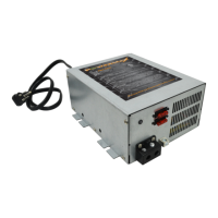
AC to DC Converter/Charger
AC to DC
CONVERTER/CHARGER
PM3 models 15, 35, 45, 55, 60, 65, 75,
100 and 120 Amp and 3 Stage
Charging Option
Installation & Maintenance
1.
DISCONNECT DC POWER.
Disconnect the battery POS (+) wire at the battery end before connecting this Converter/Charger to any
vehicle/device wiring.
2.
LOCATION.
The mounting location may be on any interior (out of direct weather) surface. Location chosen must be accessible after
installation. When mounted inside a cabinet, the cabinet must be large enough to allow dissipation of heated air. Make sure that there is a
minimum of 1” (one inch) free air space at each end of the unit so that cooling air can move through the unit properly. AVOID foreign
contaminants such as dirt, metal particles or moisture.
3.
MOUNTING.
Flanges with holes are provided for ease of mounting using standard fasteners. Confirm that the surface that the converter is
mounted to is solid and will hold the weight (6 lbs) during vehicle operation.
4.
ELECTRICAL REQUIREMENTS.
A
120 VAC
receptacle needs to be located within 36 inches of the Converter/Charger to supply power.
Ele
ctrical consi
deration should also be given to mounting near the locations of the batteries and the
12-volt DC
distribution panel.
5.
ELECTRICAL CONNECTIONS
. Be sure to tighten all connections securely. A loose connection can quickly cause terminals and wires to
overheat. Review unit labels for recommended terminal torque values.
7. Never Leave the PowerMax PM3-XX unattended when plugged in.
8. All PM3 Products must
be installed by a certified electrician.
FOR YOUR SAFETY, READ ALL INSTRUCTIONS BEFORE INSTALLATION AND OPERATION.
INSTALLER:
Provide these instructions to the end user or consumer.
CONSUMER:
Keep these instructions for future reference.
NOTICE: Products are not to be used nor are warranted in aerospace, medical or life safety applications.
120 VAC
is present. This Converter/Charger is designed to convert
120 VAC
to
12 VDC
. It also provides low voltage
power for charging on-board
12 VDC
batteries. The Converter/Charger is a “switch mode” type and is designed to be
maintenance-free with no user serviceable components. The Converter/Charger power output is “current limiting” by
design.
WARNING – Avoid Possible Injury or Death
NEVER store electrical devices in compartments where flammable liquids (such as gasoline) exist.
DO NOT mount/install unit in compartments designed for storage of batteries of flammable liquids.
WARNING – Avoid Personal Injury or Product Damage
6. THE FAN WILL NOT RUN ALL THE TIME. THE FAN RUNS ONLY WHEN NEEDED.