WARNING
Do not install close to appliances that are a source of heat or water such as water heaters,
furnaces or under refrigerators. They are not designed for mounting in wet locations. They must be
protected from direct contact with water and debris.
WARNING
Do not mount in zero a clearance compartment. Overheating may result. Do not drill through the
metal housing. Debris and metal shavings can interfere with the operation of the transfer switch.
For wiring, use the existing knockouts.
WARNING-MORE THAN ONE LIVE CIRCUIT-SEE DIAGRAM
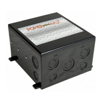
The PMTS-30 and PMTS-50 must be installed by a qualified electrician.
Operation:
When shore power is available, it is automatically connected to the Control Panel. To operate from an
onboard generator, start the generator and after 20 to 30 seconds power will automatically transfer from
shore power to generator. The time delay of 20 to 30 seconds allows the generator voltage to stabilize.
When the Generator stops, power automatically and immediately transfers back to shore power.
Wiring instructions:
The PMTS-30 is rated for use on a circuit capable of momentarily delivering not more than:
3000 rms symmetrical Amps. 240 V AC Max operating voltage
The PMTS-50 is rated for use on a circuit capable of momentarily delivering not more than:
5000 rms symmetrical Amps. 240 V AC Max operating voltage
When L1 and L2 (rated for 35 A each) are connected in phase, generator-neutral capability will increase
up to 70 A
All field wires used have to be rated for at least 105° C.
For 6 to 14 AWG wires, use 13 inch-pound torque.
Ground terminal bar is suitable for 6-14 AWG conductors using 35 inch-pounds torque. All grounds are
connected inside of the PMTS-30 and PMTS-50.
 Loading...