4
The Model 2000 nails down fl ooring from
5/16” to 9/16” using the Powernail FLEX
adjustable foot assembly that can be adjusted to
fi t different fl ooring profi les.
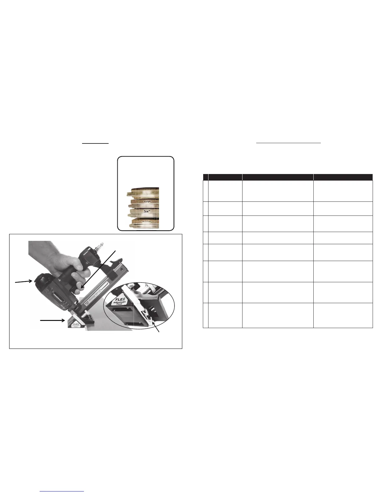
To use the Model 2000, simply snug up the
fl ooring, pull the trigger and let the nailer drive and
set the nail at the correct 45 degree angle.
The unique body design allows for different grip
angles and has an adjustable exhaust port to
redirect nailer exhaust.
OPERATION
The Model 2000
installs tongue and
groove fl ooring
from
5/16” to 9/16”
.
Adjustable
Exhaust
Port
Floor activated safety mechanism
prevents accidental tool activation.
Trigger-pull Operation!
Adjustable
FLEX Foot
Assembly
5/16"
(8 mm)
PROBLEM POSSIBLE CAUSE SOLUTION
1
Air leaking at
Trigger area
1. O-ring (31) in trigger valve is damaged.
2. Trigger valve head (30) is damaged.
3. Trigger valve stem (35), seal (29) or O-ring (31)
is damaged.
1. Check and replace O-ring.
2. Check and replace trigger
valve head.
3. Check and replace trigger valve stem,
seal or O-ring.
2
Air leaking between
body and drive guider
Damaged bumper (22). Check and replace bumper.
3
Air leaking between
body and cylinder cap
1. Screw loose (5).
2. Damaged gasket (8).
1. Tighten screws.
2. Check and replace gasket.
4
Blade driving
fastener
too deeply
1. Worn bumper (22).
2. Air pressure is too high
1. Replace bumper.
2. Adjust the air pressure.
5
Runs slowly or
has loss of power
1. Insuffi cient oil.
2. Insuffi cient air supply.
3. Broken spring in cylinder cap (8a).
4. Exhaust port (3) in cylinder cap is blocked
1. Lubricate as instructed
2. Check air supply.
3. Replace spring.
4. Replace damaged internal parts.
6
Tool skips a fastener
1. Worn bumper (22) or damaged spring (57).
2. Dirt in gate (50).
3. Inadequate airfl ow to tool.
4. Worn or dry O-ring (17) on piston.
5. Cylinder cap seal leaking (8).
1. Replace bumper or pusher spring.
2. Clean drive channel of front plate.
3. Check hose and compressor fi ttings.
4. Replace O-ring or lubricate.
5. Replace seal.
7
Fasteners are
jammed
(see page 8)
1. Joint guider is worn (24).
2. Fasteners are wrong size or damaged.
3. Magazine or front plate screws are loose (78).
4. Blade (27) in piston assembly is damaged.
1. Replace joint guider.
2. Use the recommended and
undamaged fasteners.
3. Tighten screws.
4. Replace piston assembly.
8
Tool will not drive
down tight
1. Worn blade in piston assembly.
2. Lack of power.
3. Slow cycling and loss of power.
1. Replace piston assembly.
2. Adjust to adequate air pressure.
3. Check cylinder cap spring for
broken coils or reduced length.
Check if exhaust port of cylinder
cap is restricted.
Here are some common issues that may occur during use.
If the nailer is not working as it should, stop using the tool immediately and resolve the
issue before continuing.
9
TROUBLE SHOOTING CHART
 Loading...