8
CLEARING A JAM
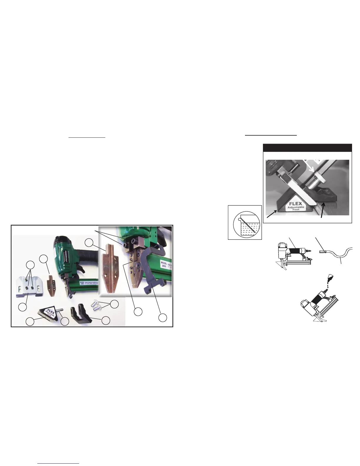
Disassembly: (See Figure 7.)
1) NOTE: Do not remove the two M5 screws (80).
2) Remove the two adjusting knobs (76) and cap screws (77).
3) Remove the support shoe (73) and foot rest (74).
4) Remove three M4 screws (78) with a 3mm allen wrench and lift off foot (71).
5) Slide the safety arm (75) to the side.
6) Lift the gate plate (72) off to clear the jam and inspect the drive blade (27) and its path.
Reassembly:
1) Make sure the drive blade (27) is centered and re-install the gate plate (72).
2) Slide the safety arm (75) back on top of the gate plate (72).
3) Install foot (71) on top of safety arm (75) and gate plate (72).
4) Install three M4 screws (78) and tighten.
5) Install support shoe (73), foot rest (74), cap screws (77), and adjusting knobs (76).
76
77
73
74
(80) DO NOT REMOVE THE TWO TOP BODY SCREWS
75
71
78
72
72
27
Figure 7.
5
CONNECTING THE TOOL TO AN AIR SUPPLY
Your air tool is fully assembled when you receive
it. Before using it, attach the air line and desired
air system accessories. Be sure the air hose
is depressurized when installing or removing
adapters to the air line. To prevent misfi re, do not
connect air to a loaded nailer.
1. An automatic airline oilier is recommended but oil may be
added manually before every operation or after about 1 hour of
continuous use.
2. Place two (2) drops of air-tool oil in the air plug as shown
(Figure 3). If you are using an automatic in-line oiler, check and
add oil if necessary.
3. Turn your compressor on and set the compressors pressure
regulator to the proper pressure for the size and type of fastener
being used. Normal operating pressure should be adjusted
between 70-110 psi based on fastener and wood being used.
4. Connect the tool to the air supply (Figure 2).
FOOT ADJUSTMENT / NAIL LOCATION
Figure 1.
Loosen both adjusting knobs
(#76, See Figure 1.)
Hold nailer on a piece of sample fl ooring
to be installed.
Adjust the foot rest (#74) so it lays fl at on
the fi nished surface of the fl ooring
(Figure 1).
Lightly snug both adjusting knobs (#76).
Push down on the support shoe (#73) so
it lays fl at on the sub fl oor.
Tighten both adjusting knobs (#76).
Test the adjustment by nailing down
a sample piece of
fl ooring.
Re-adjust the foot if
necessary so that the
nail insertion point
enters the center
of the fl ooring nail
pocket. (Figure 4).
OPERATION, continued...
Adjust the foot to a sample of your wood.
74. Foot Rest
76. Adjusting Knobs (2)
73. Support Shoe
Nailer
Quick
Connector
Figure 4.
 Loading...