USING THE SUPPORTS
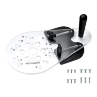
1. The supports are used with Sub Adapter (B).
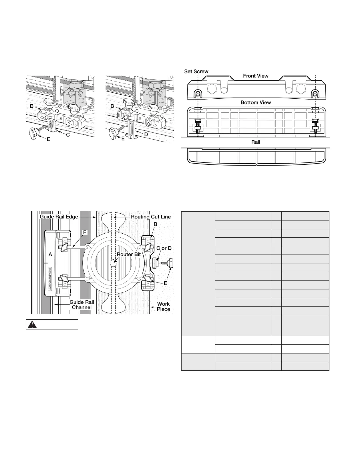
• Stepped level for Support 1 (C) is 0‑8 mm. Figure 4
• Stepped level for Support 2 (D) is 0‑33 mm. Figure 5
2. Loosely assemble the support (C or D) and an Adjustment
Screw (E).
Figure 4 Figure 5
3. Place entire assembly onto guide rail. Set and lock
adjustment screws by rst putting moderate pressure
on Adapter (A) to ensure it is set square. While pushing
down on Adapter (A), adjust the support to the top of
the work surface and tighten adjustment screws. Test
movement of the assembled router to verify it sets square
and moves smoothly.
4. Move router to desired position.
Figure 6
CAUTION
Make sure the cut line of the bit does not contact the guide rail.
ADJUSTING THE SET SCREWS
1. Remove the Guide Rail Adapter from the guide rail and turn
the two set screws shown in (Figure 7). Do not over tighten.
2. Place back on the guide rail and verify that it moves freely
with no slack.
Figure 7
NOTE: Even pressure must be applied when adjusting and
tightening set screws, if the adapter is not square it may cause
chatter during operation.
KNOWN COMPATIBLE ROUTERS
Makita*
RP0910 F 8 mm rod
RP1110C F 8 mm rod
3612 G 12 mm rod
3612C G 12 mm rod
3612BR G 12 mm rod
RP1800 G 12 mm rod
RP1801 G 12 mm rod
RP1800F G 12 mm rod
RP1801F G 12 mm rod
RP2300FC G 12 mm rod
RP2301FC G 12 mm rod
RP0900K F 8 mm rod
Compact Routers
using Plunge Base
196094-2
F 8 mm rod
DEWALT*
DW621 F 8 mm rod
DWP611PK F 8 mm rod
Ryobi*
R1631K F 8 mm rod
R163G F 8 mm rod
* DEWALT is a trademark of The Stanley Black & Decker Corporation—Makita is
a trademark of Makita Corporation—Ryobi is a trademark of Ryobi Limited and is
used by Techtronic Industries Company LTD
NOTE: Routers listed are compatible with the POWERTEC
71085 Guide Rail Adapter.
If you do not have any of the listed routers, check the through-
mounting hole measurement on your router base and compare
to the base measurements in (Figure 1) to verify if either set will
work for you.
 Loading...