GRIP PRO INSTALLATION MANUAL
6
adjuster nuts.
Chrysler® tool: C-4164
Ford® tool: T70P4067-A
9. Remove bearing cap bolts and
bearing caps.
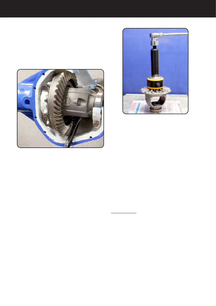
10. Remove dierential case. It may
be necessary to use a pry bar as
shown in Figure 2. Exercise caution
when prying on the carrier so that
the gasket sealing surface is not
damaged. Place shims/adjuster nuts
and bearing cups with their respective
bearing cap.
Note: Adjuster nuts will stay in the
housing in some axles.
11. Remove and discard the ring gear
bolts. With a non- metallic hammer or
brass drift punch, drive the ring gear
loose from the dierential case pilot
and remove.
12. Remove anti-lock brake tone
wheel if applicable. Consult vehicle
service manual for proper procedure.
13. Remove dierential bearing cones
from the dierential using the proper
bearing puller and adapter.
See Figure 3.
14. Clean all parts in a suitable
cleaning solvent and dry thoroughly.
Clean axle housing by pushing a
clean rag through the axle tube with
a wooden rod. Push the rag from the
end of the axle tube to the center
of the axle housing. Wipe down the
inside of the housing with a clean rag.
CAUTION: Do not spin-dry the
bearings with compressed air. Serious
damage or injury may result.
15. Remove any burrs from all
machined surfaces in the axle
housing, bearing cap and ring gear.
16. Inspect axle shaft bearing surface,
bearings and seals. Replace if
needed.
Figure 3
Figure 2