GRIP PRO INSTALLATION MANUAL
7
17. Inspect dierential bearings and
replace if needed. Always replace
both the cup and cone as a set from
the same manufacturer.
18. Thoroughly clean the dierential
bearing hubs and ring gear mounting
ange prior to installation of the
bearings and ring gear.
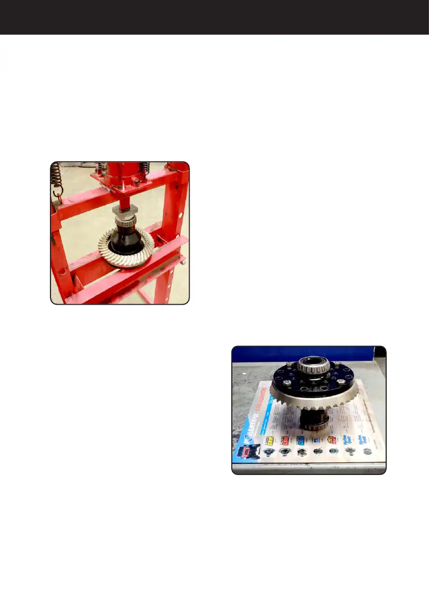
19. Install the dierential bearing
cones onto the bearing hubs of the
dierential case using the proper
installation tool. See Figure 4.
Note: Many Dana® applications use
shims between the bearing cone
and the dierential case bearing hub
shoulder. The bearing cones must be
removed to make adjustments to the
shim pack thickness.
20. For adjuster nuts, skip to Step 23.
21. Install dierential with the bearing
cups and shims into the dierential
housing. Adjust the shim pack as
necessary to create a slip t of
the dierential into the dierential
housing. A slip t is the thickest
shim pack that can be installed by
hand with slight resistance. It will be
necessary to rotate the dierential
case after each shim thickness
change to seat the bearings.
22. Remove the dierential from the
dierential housing. Measure the
combined thickness of the shims. This
total shim thickness is what is needed
for installing the dierential (prior to
adding preload to the bearings).
23. Heat the ring gear and anti-lock
tone wheel (if applicable) with a heat
lamp or by submersing in hot water.
Do not exceed 300º F. Do not use a
torch!
24. Install anti-lock tone wheel (if
applicable) while hot onto the outside
diameter of the dierential ring gear
ange as stated in the vehicle service
manual.
25. Install the ring gear while hot onto
the dierential. Use pilot studs to align
the ring gear to the dierential as
shown in Figure 5.
Figure 4
Figure 5
 Loading...