1 – INTRODUCTION: TECHNICAL FEATURES OF THE
ELECTRONIC SYSTEM
All the parameters of the Triex Connect Dupla control unit can be set
through the PROG programmer (programming tool) in three languages
(Portuguese, English or Spanish) or PPA's BLUE. It can be used on all
models of PPA operators with induction motors.
It is endowed with an EEProm¹ memory that ores all codes of the
remote controls in an encrypted form, as well as the control unit
operation parameters, such as the deceleration zone, pause time etc.
The unit control is also compatible to Rolling Code Remote Controls
with PPA's own protocol.
The syem can be activated by remote control through a bult-in
radiofrequence receiver, a loose receiver or any other device with a NO
(Normally Open) contact as, for example, a pushbutton.
Triex Connect Dupla is the ideal unit control to be used with a PPA UPS.
It has some features that can reduce the energy consumption when it
is operating o a battery.
The gate position control is achieved through an encoder syem
patented by PPA called “Reed Digital”.
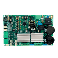
2 – CONTROL UNIT
2.1 – ELECTRICAL CONNECTIONS
The General Wiring Diagram can be seen below.
2.2 – SYSTEM POWER SUPPLY
The operator mu be connected to the power grid through the L and N
inputs on the power terminal block, 110 - 220VAC connector, according
to picture 1.
Warning: The operator is dual voltage (auto range); one has only to
plug it into a 110 / 220V power supply; the utility frequency can be
either 60Hz or 50Hz.
2.3 – INDUCTION MOTOR CONNECTION
The three cables on the induction motor mu be connected to the
“MOTOR1” and “MOTOR2” terminal blocks. THERE IS NO CORRECT
COLOR SEQUENCE
2
. Motor 2 is factory set as the 'delay' motor.
2.4 – CONNECTING THE “ENC1” AND "ENC2" ENCODERS
It is used to connect the encoder, by using a proper cable, between
the motor and the control unit. Inside the operator gearbox there
are sensors that provide the unit control with information about the
movement direction and the position of the gate during the operation.
Such information is essential for the automator's proper operation.
There are two sensors inside the encoder and each one is represented
by the LEDs ECA1, ECB1, ECA1 and ECB2. Each one ashes according to
the corresponding position of the disc.
2.5 – CONNECTING THE “TRV” ELECTROMAGNETIC LOCK
If one decides to use an (optional) electromagnetic lock, one mu
connect the “Optional Relay Module” to this connector. The control
unit will also recognize the module automatically and a time interval
(used to art the opening movement of the operator after activating
the electromagnetic lock) will be added.
2.6 – CONNECTING THE “LUZ” COURTESY LIGHT
If one decides to use courtesy light, one mu connect the “Optional
Relay Module” to this connector. By doing so, the operation of the
courtesy light is always enabled.
One mu set the desired time through the DIP switch.
2.7 – CONNECTING THE “RX” LOOSE RECEIVER
A loose receiver can be added to the control unit through the “RX”
connector.
Quando um comando é aceito, um LEDCMD (comando) correspondente
é acionado. O Jumper “HRF” deve ser retirado quando o receptor avulso
é adicionado ao siema de forma a desligar o receptor incorporado.
CAUTION: Before connecting the optional accessories (Elec-
tromagnetic lock and/or Courtesy Light / Traffic Light (Visual Exit
Annunciator), pushbuttons etc), we strongly recommend testing
the general operation of the product. To do so, send a command
to the operator to start the self-learning cycle.
2.8 – "FOT" CLOSING PHOTOCELL CONNECTION
This is a dedicated input port for the 'closing photocell', which is
a sensor that detects an obacle during the gate's closing cycle,
preventing the gate to move if there is an obacle along its course. If
there is a blockage during the closing cycle, the operator reverses its
movement to the opposite direction.
The photocells should be inalled about 50 cm (1.65 ft) above the
ground (in accordance with the manufacturer's recommendation), in
such a way that the both the transmitter and the receiver are aligned
between each other. The electrical connections mu be as follows:
Terminal block 2: 15V (positive "+");
Terminal block 1: GND (negative "-");
Terminal block 3: FOT (Contact of the Photocell).
2.9 – "FAB" OPENING PHOTOCELL CONNECTION
This is a dedicated input port for the 'opening photocell', which is
a sensor that detects an obacle during the gate's opening cycle,
preventing the gate to move if there is an obacle along its course.
If there is a blockage during the opening cycle, the operator ops
moving.
The photocells should be inalled about 50 cm (1.65 ft) above the
ground (in accordance with the manufacturer's recommendation), in
such a way that the both the transmitter and the receiver are aligned
between each other. The electrical connections mu be as follows:
Terminal block 2: 15V (positive "+");
Terminal block 1: GND (negative "-");
Terminal block 4: FAB (Contact of the Photocell).
CAUTION: This control unit is compatible with any kind of photocell
(Normally Open, Normally Closed or Resistive). In order to set the photo-
cell intended to be used, one must connect all photocells and press the
“RAMPA” (Deceleration zone) button, with all photocell aligned, i.e., with
no obstacle between them. One can also calibrate the photocells by using
the PROG programmer (programming tool). To do so, one must enter the
“Calibration” function and press the “+” button on the device’s keypad.
There are LEDs used for checking the commands by the opening (“FA”)
and closing (“FF”) photocells.
2.10 – CONNECTING THE “BOT” PUSHBUTTON
The control unit acknowledges (recognizes) a pushbutton command
when the BOT Terminal block is connected to the GND, i.e., a pulse
to the GND.
Terminal block 1: GND (Negative "-");
Terminal block 4: BOT (NO Contact).
There is a LED used for checking the pushbutton commands ("BOT").
2.11 – CONNECTING THE “ABR” OPENING-ONLY PUSHBUTTON
The control unit acknowledges an opening command when the "ABR"
Terminal block is connected to the GND, i.e., a pulse to the GND.
Terminal block 1: GND (Negative "-");
Terminal block 5: ABR (NO Contact).
There is a LED used for checking the pushbutton commands ("ABR").
2.12 – CONNECTING THE “FEC” CLOSING-ONLY PUSHBUTTON
The control unit acknowledges a closing command when the "FEC"
Terminal block is connected to the "GND" and then released, i.e., a pulse
to the GND and the the button mu be released.
It makes it easier using the control unit in access control syems that
use photocells or inductive loops to automatically close the gate or
automatic barrier.
Terminal block 1: GND (Negative "-");
Terminal block 6: FEC (NO Contact).
There is a LED used for checking the "FEC" terminal block commands.
WARNING
The logic controller provides 15V (400 mA maximum DC Cur-
rent) to power the photocells and receivers. If the devices need
increased voltage or current, using an auxiliary power supply
will be necessary.
2.13 – CONNECTING THE “HIB1” AND "HIB2" LIMIT SWITCH SENSOR
REEDS
The control unit acknowledges a “reed” activated when the pin
corresponding to it on the HIB male pin header is connected to the
GND, i.e., a pulse to the GND.
The only condition to be observed is that the reed corresponding to
the gate open mu be connected in such a way that the “RDA1” LED
lights to the motor connector to the "MOTOR1" terminal block, pin of
the connector “HIB” marked with the letter “A”. And the “RDF1” LED
to the motor connected to the "MOTOR1" mu light when the gate is
closed, pin of the connector “HIB” marked with the letter “F”. The same
procedure mu be carried out to the second motor, connected to the
"MOTOR2" terminal block.
2.14 – “PROG” CONNECTOR
Connector used for communication between the control unit, and the
PROG or BLUE programmers (programming tools).
2.15 – “INFO_UPS” CONNECTOR
This connector is used as the communication between the control
unit and the PPA UPS. With this connection inalled, the control unit
improves the operation when it is working without power grid supply,
i.e., o the batteries.
Their improvements are:
1 – The control unit reduces the energy consumption when the
motor is switched on; this is accomplished by decreasing the
working speed, reaching up to a 50% decrease;
2 – When the control unit is in Stand-By mode, the gate is either
open or closed, and the motor is switched o, it sends a command
to the UPS to turn the power amplier o and to reduce the
battery consumption, increasing the autonomy in such situations.
With this feature, it is possible to run out of electric energy for
several hours without draining the battery. Only the RF receiver
and the activation commands are powered directly o the battery,
what allows the control unit to receive a command and afterwards
the PPA UPS turns the voltage elevator on and the operator arts
operating. This syem is patented by PPA.
3 – GATE SYSTEMS' LOGIC FUNCTION
3.1 – FIRST ACTIVATION AFTER INSTALLATION (ACQUIRING / SELF-
LEARNING)
When the inverter is powered for the r time, after being inalled to
the operator, the gate mu be on the middle of its travel, and mu
art an opening movement after an external command or if the button
“CMD” has been pressed.
If it is a closing movement, open the F/R jumper to change the direction
of operation of the motor. If the F/R jumper is closed again, the direction
of operation returns to the previous one.
That done, press the “CMD” button or send an external command to
the control unit.
Afterwards, let the gate open until it leans on the opening opper or
until it activates the 'REEDA'. Then, it will reverse the direction to close;
let it lean on the closing opper or activate the 'REEDF'.
WARNING: The gate operator can operate only with ENCODER or
ENCODER plus REED, but cannot operate with REED only. When the
gate is closing during the self-learning, only a photocell command can
reverse the gate movement.
The automatic gate is now ready to operate.
Note: If the swing gate is endowed with a rabbet (metal rip to hold one
of the leaves), one mu enable a motor delay through PROG. The delay
will be enabled on Motor 2.
3.2 – FROM THE SECOND ACTIVATION ON, WHEN THE CONTROL
UNIT IS DISCONNECTED FROM THE POWER SUPPLY
After the previous operation, the gate will not need to acquire
(memorize) the travel again. It will simply and slowly close after a
command, until it leans on the closing opper; the motor will turn itself
o after a couple seconds. The automatic gate is now ready to operate.
In case the photocell beam is obructed or the control unit receives a
command during this r closing movement, the reference point to be
sought will be the opening one, in order to accelerate the acquiring of
a known point of the gate's travel.
1
EEPROM (from Electrically-Erasable Programmable Read-Only Memory) is a non-volatile
oring chip used in computers and other electronic devices.
2
Refer to item 3.1 – FIRST ACTIVATION AFTER INSTALLATION (ACQUIRING / SELF-LEARNING).
SYSTEM
GROUNDING
(85V - 265V)
(50Hz - 60Hz)
POWER SUPPLY
PROGRAMMING
BUTTONS
ANALOG LIMIT
SWITCH REED
(MASTER MOTOR)
OPTIONAL
'ALCANCE'
RECEIVER
PPA UPS
COMMUNICATION
(OPTIONAL)
COURTESY LIGHT
PROG
(OPTIONAL) LOCK
INDUCTION MOTOR
(SLAVE)
M
M
INDUCTION MOTOR
(MASTER)
RECEIVER JUMPER
CLOSED = ENABLES RF
OPEN = DISABLES RF
ANALOG LIMIT SWITCH
REED (SLAVE MOTOR)
ENCODER CABLE (MOTOR 1)
ENCODER CABLE (MOTOR 2)
P07109 - 01/2022
Rev. 2
TRIFLEX CONNECT DUPLA
CONTROL BOARD
TECHNICAL MANUAL
WARNING
Do not use the equipment
without referring to this
manual first.
Made by: Motoppar Indústria e Comércio de Automatizadores Ltda
Av. Dr. Labieno da Costa Machado, 3526 - Distrito Industrial
Garça - SP - CEP 17406-200 - Brasil
CNPJ: 52.605.821/0001-55
www.ppa.com.br | +55 14 3407 1000
1 – INTRODUCTION: TECHNICAL FEATURES OF THE
ELECTRONIC SYSTEM
All the parameters of the Triex Connect Dupla control unit can be set
through the PROG programmer (programming tool) in three languages
(Portuguese, English or Spanish) or PPA's BLUE. It can be used on all
models of PPA operators with induction motors.
It is endowed with an EEProm¹ memory that ores all codes of the
remote controls in an encrypted form, as well as the control unit
operation parameters, such as the deceleration zone, pause time etc.
The unit control is also compatible to Rolling Code Remote Controls
with PPA's own protocol.
The syem can be activated by remote control through a bult-in
radiofrequence receiver, a loose receiver or any other device with a NO
(Normally Open) contact as, for example, a pushbutton.
Triex Connect Dupla is the ideal unit control to be used with a PPA UPS.
It has some features that can reduce the energy consumption when it
is operating o a battery.
The gate position control is achieved through an encoder syem
patented by PPA called “Reed Digital”.
2 – CONTROL UNIT
2.1 – ELECTRICAL CONNECTIONS
The General Wiring Diagram can be seen below.
2.2 – SYSTEM POWER SUPPLY
The operator mu be connected to the power grid through the L and N
inputs on the power terminal block, 110 - 220VAC connector, according
to picture 1.
Warning: The operator is dual voltage (auto range); one has only to
plug it into a 110 / 220V power supply; the utility frequency can be
either 60Hz or 50Hz.
2.3 – INDUCTION MOTOR CONNECTION
The three cables on the induction motor mu be connected to the
“MOTOR1” and “MOTOR2” terminal blocks. THERE IS NO CORRECT
COLOR SEQUENCE
2
. Motor 2 is factory set as the 'delay' motor.
2.4 – CONNECTING THE “ENC1” AND "ENC2" ENCODERS
It is used to connect the encoder, by using a proper cable, between
the motor and the control unit. Inside the operator gearbox there
are sensors that provide the unit control with information about the
movement direction and the position of the gate during the operation.
Such information is essential for the automator's proper operation.
There are two sensors inside the encoder and each one is represented
by the LEDs ECA1, ECB1, ECA1 and ECB2. Each one ashes according to
the corresponding position of the disc.
2.5 – CONNECTING THE “TRV” ELECTROMAGNETIC LOCK
If one decides to use an (optional) electromagnetic lock, one mu
connect the “Optional Relay Module” to this connector. The control
unit will also recognize the module automatically and a time interval
(used to art the opening movement of the operator after activating
the electromagnetic lock) will be added.
2.6 – CONNECTING THE “LUZ” COURTESY LIGHT
If one decides to use courtesy light, one mu connect the “Optional
Relay Module” to this connector. By doing so, the operation of the
courtesy light is always enabled.
One mu set the desired time through the DIP switch.
2.7 – CONNECTING THE “RX” LOOSE RECEIVER
A loose receiver can be added to the control unit through the “RX”
connector.
Quando um comando é aceito, um LEDCMD (comando) correspondente
é acionado. O Jumper “HRF” deve ser retirado quando o receptor avulso
é adicionado ao siema de forma a desligar o receptor incorporado.
CAUTION: Before connecting the optional accessories (Elec-
tromagnetic lock and/or Courtesy Light / Traffic Light (Visual Exit
Annunciator), pushbuttons etc), we strongly recommend testing
the general operation of the product. To do so, send a command
to the operator to start the self-learning cycle.
2.8 – "FOT" CLOSING PHOTOCELL CONNECTION
This is a dedicated input port for the 'closing photocell', which is
a sensor that detects an obacle during the gate's closing cycle,
preventing the gate to move if there is an obacle along its course. If
there is a blockage during the closing cycle, the operator reverses its
movement to the opposite direction.
The photocells should be inalled about 50 cm (1.65 ft) above the
ground (in accordance with the manufacturer's recommendation), in
such a way that the both the transmitter and the receiver are aligned
between each other. The electrical connections mu be as follows:
Terminal block 2: 15V (positive "+");
Terminal block 1: GND (negative "-");
Terminal block 3: FOT (Contact of the Photocell).
2.9 – "FAB" OPENING PHOTOCELL CONNECTION
This is a dedicated input port for the 'opening photocell', which is
a sensor that detects an obacle during the gate's opening cycle,
preventing the gate to move if there is an obacle along its course.
If there is a blockage during the opening cycle, the operator ops
moving.
The photocells should be inalled about 50 cm (1.65 ft) above the
ground (in accordance with the manufacturer's recommendation), in
such a way that the both the transmitter and the receiver are aligned
between each other. The electrical connections mu be as follows:
Terminal block 2: 15V (positive "+");
Terminal block 1: GND (negative "-");
Terminal block 4: FAB (Contact of the Photocell).
CAUTION: This control unit is compatible with any kind of photocell
(Normally Open, Normally Closed or Resistive). In order to set the photo-
cell intended to be used, one must connect all photocells and press the
“RAMPA” (Deceleration zone) button, with all photocell aligned, i.e., with
no obstacle between them. One can also calibrate the photocells by using
the PROG programmer (programming tool). To do so, one must enter the
“Calibration” function and press the “+” button on the device’s keypad.
There are LEDs used for checking the commands by the opening (“FA”)
and closing (“FF”) photocells.
2.10 – CONNECTING THE “BOT” PUSHBUTTON
The control unit acknowledges (recognizes) a pushbutton command
when the BOT Terminal block is connected to the GND, i.e., a pulse
to the GND.
Terminal block 1: GND (Negative "-");
Terminal block 4: BOT (NO Contact).
There is a LED used for checking the pushbutton commands ("BOT").
2.11 – CONNECTING THE “ABR” OPENING-ONLY PUSHBUTTON
The control unit acknowledges an opening command when the "ABR"
Terminal block is connected to the GND, i.e., a pulse to the GND.
Terminal block 1: GND (Negative "-");
Terminal block 5: ABR (NO Contact).
There is a LED used for checking the pushbutton commands ("ABR").
2.12 – CONNECTING THE “FEC” CLOSING-ONLY PUSHBUTTON
The control unit acknowledges a closing command when the "FEC"
Terminal block is connected to the "GND" and then released, i.e., a pulse
to the GND and the the button mu be released.
It makes it easier using the control unit in access control syems that
use photocells or inductive loops to automatically close the gate or
automatic barrier.
Terminal block 1: GND (Negative "-");
Terminal block 6: FEC (NO Contact).
There is a LED used for checking the "FEC" terminal block commands.
WARNING
The logic controller provides 15V (400 mA maximum DC Cur-
rent) to power the photocells and receivers. If the devices need
increased voltage or current, using an auxiliary power supply
will be necessary.
2.13 – CONNECTING THE “HIB1” AND "HIB2" LIMIT SWITCH SENSOR
REEDS
The control unit acknowledges a “reed” activated when the pin
corresponding to it on the HIB male pin header is connected to the
GND, i.e., a pulse to the GND.
The only condition to be observed is that the reed corresponding to
the gate open mu be connected in such a way that the “RDA1” LED
lights to the motor connector to the "MOTOR1" terminal block, pin of
the connector “HIB” marked with the letter “A”. And the “RDF1” LED
to the motor connected to the "MOTOR1" mu light when the gate is
closed, pin of the connector “HIB” marked with the letter “F”. The same
procedure mu be carried out to the second motor, connected to the
"MOTOR2" terminal block.
2.14 – “PROG” CONNECTOR
Connector used for communication between the control unit, and the
PROG or BLUE programmers (programming tools).
2.15 – “INFO_UPS” CONNECTOR
This connector is used as the communication between the control
unit and the PPA UPS. With this connection inalled, the control unit
improves the operation when it is working without power grid supply,
i.e., o the batteries.
Their improvements are:
1 – The control unit reduces the energy consumption when the
motor is switched on; this is accomplished by decreasing the
working speed, reaching up to a 50% decrease;
2 – When the control unit is in Stand-By mode, the gate is either
open or closed, and the motor is switched o, it sends a command
to the UPS to turn the power amplier o and to reduce the
battery consumption, increasing the autonomy in such situations.
With this feature, it is possible to run out of electric energy for
several hours without draining the battery. Only the RF receiver
and the activation commands are powered directly o the battery,
what allows the control unit to receive a command and afterwards
the PPA UPS turns the voltage elevator on and the operator arts
operating. This syem is patented by PPA.
3 – GATE SYSTEMS' LOGIC FUNCTION
3.1 – FIRST ACTIVATION AFTER INSTALLATION (ACQUIRING / SELF-
LEARNING)
When the inverter is powered for the r time, after being inalled to
the operator, the gate mu be on the middle of its travel, and mu
art an opening movement after an external command or if the button
“CMD” has been pressed.
If it is a closing movement, open the F/R jumper to change the direction
of operation of the motor. If the F/R jumper is closed again, the direction
of operation returns to the previous one.
That done, press the “CMD” button or send an external command to
the control unit.
Afterwards, let the gate open until it leans on the opening opper or
until it activates the 'REEDA'. Then, it will reverse the direction to close;
let it lean on the closing opper or activate the 'REEDF'.
WARNING: The gate operator can operate only with ENCODER or
ENCODER plus REED, but cannot operate with REED only. When the
gate is closing during the self-learning, only a photocell command can
reverse the gate movement.
The automatic gate is now ready to operate.
Note: If the swing gate is endowed with a rabbet (metal rip to hold one
of the leaves), one mu enable a motor delay through PROG. The delay
will be enabled on Motor 2.
3.2 – FROM THE SECOND ACTIVATION ON, WHEN THE CONTROL
UNIT IS DISCONNECTED FROM THE POWER SUPPLY
After the previous operation, the gate will not need to acquire
(memorize) the travel again. It will simply and slowly close after a
command, until it leans on the closing opper; the motor will turn itself
o after a couple seconds. The automatic gate is now ready to operate.
In case the photocell beam is obructed or the control unit receives a
command during this r closing movement, the reference point to be
sought will be the opening one, in order to accelerate the acquiring of
a known point of the gate's travel.
1
EEPROM (from Electrically-Erasable Programmable Read-Only Memory) is a non-volatile
oring chip used in computers and other electronic devices.
2
Refer to item 3.1 – FIRST ACTIVATION AFTER INSTALLATION (ACQUIRING / SELF-LEARNING).
SYSTEM
GROUNDING
(85V - 265V)
(50Hz - 60Hz)
POWER SUPPLY
PROGRAMMING
BUTTONS
ANALOG LIMIT
SWITCH REED
(MASTER MOTOR)
OPTIONAL
'ALCANCE'
RECEIVER
PPA UPS
COMMUNICATION
(OPTIONAL)
COURTESY LIGHT
PROG
(OPTIONAL) LOCK
INDUCTION MOTOR
(SLAVE)
M
M
INDUCTION MOTOR
(MASTER)
RECEIVER JUMPER
CLOSED = ENABLES RF
OPEN = DISABLES RF
ANALOG LIMIT SWITCH
REED (SLAVE MOTOR)
ENCODER CABLE (MOTOR 1)
ENCODER CABLE (MOTOR 2)
P07109 - 01/2022
Rev. 2
TRIFLEX CONNECT DUPLA
CONTROL BOARD
TECHNICAL MANUAL
WARNING
Do not use the equipment
without referring to this
manual first.
Made by: Motoppar Indústria e Comércio de Automatizadores Ltda
Av. Dr. Labieno da Costa Machado, 3526 - Distrito Industrial
Garça - SP - CEP 17406-200 - Brasil
CNPJ: 52.605.821/0001-55
www.ppa.com.br | +55 14 3407 1000
WARNING
In Hybrid mode, i.e., REED plus ENCODER, if the gate is located
in one of the REEDs, the gate will start with full speed, without
needing to acquire the gate’s travel (path).
CAUTION: It is important to install fixed opening and closing
stoppers on the gate that will be automated.
4 – PROGRAMMING THE INVERTER PARAMETERS
4.1 – 'TST' FUNCTION
When the 'TST' DIP switch is turned on, the control unit enters in an
operation mode which allows one to place the operator in a specic
point of its travel (path) in order to set the limit switch limits or even to
check the mechanical part.
In this operation mode, whenever one presses the 'VFC' button, the
motor 1 is activated clockwise while the button is being pressed; once
it is released, the motor turns itself o, and when the 'TX' button is
pressed, the motor operates counteclockwise. The 'VEL' and 'PAUSA'
buttons have the same functions, respectively, to the motor 2.
4.3 – ADJUSTING PARAMETERS THROUGH THE 'TACTLED SYSTEM'
The control unit is also endowed with quick access functions through its
buttons. When the 'PROG' jumper is closed, one can press the button
corresponding to the desired function in order to set it. In order to
increase the values, one can press the button again until one reaches
the desired level. There are eight levels; the LEDs from N1 up to N8
indicate the respective level. If one wants to decrease the value, one can
press the same button until the LEDs go o and art from the r again.
In order to change another parameter, press the desired button and
repeat the procedure.
In order to save the changes, one can open the 'PROG' jumper. The gate
can now operate normally.
Programming Functions Table:
Button Function Description
“VFC”
Limit switch travel speed
Speed near the oppers.
It has an interval of 5 Hz, from 10Hz up to 50Hz.
Note: The acquiring (memorization, self-learning) speed
is the same as the limit switch, since it is larger than 20
Hz; in case it is smaller, the control board automatically
uses 20 Hz during the acquiring procedure.
“TX”
Function for adding and erasing remote controls
(TX)
1 – Adding: In order to add a remote control, press a
button of the desired remote control; then, observe that
the 'SN' LED quickly ashes if it is receiving the signal.
Press the 'TX' button again to add the control. Observe
that the 'SN' LED remains lit when it receives a signal
already added to the control unit.
2 – Erasing: In order to erase the remote controls
added to the memory, press the 'TX' button for 10
seconds; observe that the 'SN' LED ashes every one
second. After the 10-second interval has elapsed, the
'SN' LED ops timing; at this moment, all added remote
controls have been erased.
“VEL”
Speed
Adjus the opening / closing speed of the gate.
Note: It has an interval of 10Hz, from 60Hz up to 140Hz.
“PAUSA”
Semi-automatic function/Pause time on automatic
mode.
It has an interval of 30 seconds, from 0 second up to
180 seconds. When '0' is chosen, the operator becomes
semi-automatic.
“LG”
Courtesy Light time.
Selects the time the 'LG' output remains active after the
gate has closed. It has an interval of 30 seconds, from 0
second up to 240 seconds.
“RAMPA”
Close Limit Switch.
Increases or decreases the speed the operator arts
decelerating on closing and opening. It has an 8-level
adjument.
Additional functions can be programmed through the PROG
programmer (Programming tool).
5 – CLEAR (ERASE) THE MEMORIZED TRAVEL (PATH)
To clear the memorized travel of the gate, press the 'CMD' button and
hold it pressed until the 'SN' LED gets lit. When the button is released,
the memorized travel is cleared.
Note: The 'PROG' jumper mu be open.
6 – RESTORING THE FACTORY SET DEFAULTS
To reore the factory settings, press the 'CMD' button until the 'SN' LED
gets lit; do not release it; hold it pressed until the 'SN' LEd arts ashing.
When the button is released, the memorized travel is cleared, and the
factory settings are reored.
Note: The 'PROG' jumper mu be open.
7 – ADDING AN RF TRANSMITTER
In order to add an RF transmitter, press the button on the transmitter
and hold it pressed for at lea 2 seconds. After the two seconds have
elapsed, press the 'CMD' button on the control board. Observe that
before the transmitter has been added, the 'SN' LED was quickly
ashing; afterwards, it remains lit (on) during the transmission. A
maximum 256 Fixed Code (FC) or Rolling Code (RC) can be added.
8 – ERASING ALL ADDED RF TRANSMITTERS
In order to erase all added RF transmitters, close the 'PROG' jumper,
press and release the 'TX' button once and then press it again and hold
it pressed for 10 seconds; observe that the 'SN' LED ashes every one
second. After the ten seconds have elapsed, the 'SN' LED ops timing;
at this moment all added transmitters will have been erased.
9 – SELECTING THE RF RECEPTION PROTOCOL (FC/RC)
The control board is factory set to receive a Fixed Code from the remote
controls; in order to select the reception protocol in Rolling Code mode
(RC), ju activate the 'CR/CF' DIP Switch.
Caution: Whenever the ate of this DIP Switch is changed, from FC
to RC or vice versa, the previous described procedure, 'ERASING ALL
ADDED RF TRANSMITTERS' mu be repeated.
10 – ANTI-CRUSH SYSTEM
The anti-crush feature detects the presence of obacles on the gate
travel (path). During a normal operation cycle, if an obacle is detected,
the syem will do as follows:
a) When closing: the gate is activated on the opening direction.
b) When opening: The motor is turned o and it waits to receive a
command to art closing.
On the acquiring (self-learning) cycle, the anti-crush feature only has
the function of recognizing the opening and closing limit switches, i.e.,
the point in the travel where an obacle has been detected will be
considered a limit switch.
WARNING
This anti-crush system is not enough to avoid accidents with
people and pets; therefore, using photocells on the operators
is mandatory.
11 – ENCODER OPERATION TEST
It is possible to te the automators' encoders. In order to do so, ju
connect them to the control unit and check if the 'ECA1' and 'ECB1' or
the 'ECA2' and 'ECB2' LEDs ash whenever the automator is operating.
Each LED corresponds to a sensor; for example, the 'ECA1' LED
corresponds to the sensor 'A' inside the gearmotor 1.
NOTE: For the product to function properly, if it is necessary
to splice the encoder cable, we strongly recommend using a
four-wire cable, each wire being at least 1 mm. The passage of the
encoder cable in the conduit must be separate from the motor
cable, to avoid interference.
12 – EVENT / FAULT INDICATORS
12.1 – MICROCONTROLLER OPERATION INDICATION
The main function of the 'SN' LED is to indicate that the board
microcontroller is properly working; it ashes with a xed frequency
(~1Hz), since it is connected to a power supply.
12.2 – MOTOR OVERCURRENT OR SHORT-CIRCUIT INDICATION
The 'SN' LED rapidly ashes in order to warn that the power amplier
has disarmed due to overcurrent or short-circuit on the motor. The
control unit can operate normally 10 seconds after the Overcurrent.
12.3 – OVERHEATING INDICATION
The 'FC' LED rapidly ashes to warn that the power amplier has
disarmed due to overheating of the heat sink or environment. The
operator will only be able to operate again if the temperature decreases
to less than 100ºC (212° F).
12.4 – LACK OF EEPROM INDICATION
The 'SN' LED ashes twice whenever the memory is absent.
12.5 – EEPROM WITH INVALID DATA INDICATION
The 'SN' LED ashes three times whenever the memory is present but
has a content which the microcontroller does not identify as a Valid
Transmitter Code.
12.6 – OPEN LIMIT SWITCH INDICATION
The 'FC' LED ashes whenever the gate is in an open limit switch area.
12.7 – CLOSED LIMIT SWITCH INDICATION
The 'FC' LED remains lit whenever the gate is in a closed limit switch
area.
12.8 – LOAD ON THE CAPACITORS INDICATION
The 'BUS' LED indicates there is a load on the capacitors of the power
amplier.
Caution: One mu not touch the power area (capacitors area) of
the board whenever this LED is lit, even after the inverter has been
disconnected from the power supply!
12.9 – COMMANDS INDICATION
The 'FA', 'BOT', 'FF', 'ABR' and 'FEC' LEDs indicate that the control unit
is receiving a command from any of the digital inputs, such as 'ABR',
'FEC', 'BOT' or 'FOT'.
13 – FUNCTIONS ACCESSIBLE THROUGH PROG
Add a remote control
This function is used for both adding remote
control and removing (erasing, deleting)
them. In order to add one, one has to
press a button on the remote control for 2
seconds and them press the '+' button to
add it. Repeat the procedure for the other
buttons to add them to the control unit
memory (optional).
In order to remove all remote controls, press
both '-' and '+' buttons simultaneously
and keep them pressed until the message
“Memória Vazia!” (Empty Memory) appears
on the display.
Pause time
Pause time in automatic mode; when a
0-second time is selected, it enters semi-
automatic mode.
Closing ramp
(deceleration zone)
Area in which the gate arts decelerating
prior to the closing.
Opening ramp
(deceleration zone)
Area in which the gate arts decelerating
prior to the opening.
Opening speed
Frequency applied to the motor in order to
open the gate.
Closing speed
Frequency applied to the motor in order to
close the gate.
Opening ramp speed
Speed applied to the motor on the area near
the open gate.
Closing ramp speed
Speed applied to the motor on the area near
the closed gate.
Strength (Force)
applied to the motor
With this function, it is possible to apply a
lower rength to the operator to meet anti-
crush syems' requirements.
Strength (Force) in low
speed
Strength applied to the motor when in low
rotation, deceleration area.
Courtesy Light time
Countdown (Timer) which automatically
turns the courtesy light o after the gate
has closed.
Follow Photocell
Mode
Function used to automatically close the
gate after a vehicle passes through the
photocell beam. When 0 second is selected,
the function is deactivated. With a time
dierent from 0, the gate arts closing after
all sensors are clear and all preset times
had been elapsed. In case any sensor is
obructed, the timing is reset.
Stop on opening
This function is usually enabled in gated
communities, in order to avoid that the gate
ops during the opening maneuver, due
to commands from remote controls from
several residents at the same time.
Lock pulse on closing
This function enables the lock during
a closing maneuver in order to retract
its pin (for gates which do not have the
mechanical device that pushes the pin of the
electromagnetic lock at the moment).
Motor arting speed
This function adjus the r speed applied
to the motor during any beginning of
movement; it usually is lower in order to
avoid a peak of energy consumption on
arting and provides it with increased
security in case the encoder is desconnected
or damaged.
Stoppers' gap
Function for syems using 'ReedDigital' only,
in order to avoid that the operator switches
itself o with the gearmotor too pressed
again the (opening and closing) oppers.
It reduces wear and tear of the pinion and
other mechanical components.
Caution: When the syem is hybrid (Encoder
plus magnetic reed), this function is
automatically set to zero, since the magnetic
reed determines where the gate ops.
Operator model
Function which applies initial values to the
parameters closer to the operator being
used.
Photocell Input ports
calibration
This function calibrates the input ports of
the photocells. To do so, one mu connect
all protection devices to the 'FA' and 'FF'
input ports, keep all devices level (aligned
/ without obruction) and press the button
'+'.
Language
PROG's Language selection, available in
Portuguese, English and Spanish.
Slave delay
Slave gearmotor delay (Motor 2). The time
set here is used to wait to move the motor
2. During closing it is inverted, i.e., motor 2
closes r and then it waits to art closing
motor 1.
14 – TROUBLESHOOTING
Symptoms Probable Cause(s) Action(s)
The gate does not
correspond to the
travel where it has
been inalled (It
brakes before the
closing opper or
slams when closing).
There is a
memorized travel
dierent from the
travel of the place
where it has been
inalled.
Press both 'CMD'
buttons at the same
time and hold them
pressed until the 'SN'
LED lights.
Gate remains open
and when it receives
a command for
opening, it closes.
Acquiring
(Memorization)
hasn't been
performed properly.
Refer to item 3.1
Fir activation
after inallation
(Acquiring / Self-
learning).
'SN' LED quickly
ashing and the
motor shuts o.
Current sensor
activated. This might
happen when there
is a problem with the
motor.
Check the resior
of the ator. Check
the motor current
(it mu be less than
3A RMS (Average)
and 5A RMS (peak)
(Maximum 2
seconds)).
WARNING
To install digital systems such as encoders, photocells, among
others, it is recommended that the network piping electrical
or connecting cables be separated from the engine to avoid
possible eletronic noise.
GENERAL TERMS AND CONDITIONS OF WARRANTY
MOTOPPAR, Indury and Commerce of Automatic Gate Operators Ltd., regiered with
the CNPJ (National Regiry of Legal Entities) under Number 52.605.821/0001-55, located at
3526 Dr. Labieno da Coa Machado Avenue, Indurial Dirict, Garça – SP – Brazil, Zip Code
17400-000, manufacturer of PPA Products, hereby guarantees this product again design,
manufacturing or assembly defects and/or supportively as a result of material quality aws
that could make its intended use improper or inadequate, within a legal period of ninety
days from time of acquisition, provided that the inallation inructions described in the
inruction manual are observed.
Due to the credibility and tru placed on PPA products, we will add 275 more days to the
period mentioned above, reaching a warranty period of one year, likewise counted from
the time of acquisition proven by consumer through proof of purchase (Cuomer Receipt).
In case of defect, within the warranty period, PPA responsibilities are rericted to the
repair or subitution of the product manufactured by the company, under the following
conditions:
1. Repair and readjument of equipment may only be carried out by PPA Technical
Assiance, which is qualied to open, remove, and subitute parts or components, as
well as repair defects covered by this warranty; thus, failure on observing this guideline
and the veried use of any non-original parts will cause the resignation of this warranty
on the part of the user;
2. The warranty will not extend to accessories such as cables, screw kit, xing brackets,
power supplies etc.;
3. Expenses for packaging, transportation and product reinallation will be sole
responsibility of the consumer;
4. The equipment mu be sent directly to the Company responsible for the sale
(manufacturer's representative), through the address contained in the purchase invoice,
properly packed, thus avoiding loss of the warranty;
5. Within the additional period of 275 days, visits and transportation in places where
authorized technical assiance is not available will be charged. The co of transportation
of the product and/or technician will be sole responsibility of the consumer and
6. The subitution or repair of the product does not prolong the warranty time.
This warranty will be terminated if the product:
1. Is damaged by natural agents, such as atmospheric discharges, oods, wildres,
landslides etc.;
2. Is inalled in an improper electric power supply or if it is not according to any of the
inallation inructions displayed on the manual;
3. Shows defects caused by droppings, collisions or any other physical accident;
4. Shows signs of product violation or attempted repair by unauthorized personnel;
5. Is not used for its intended purpose;
6. Is not used under normal conditions;
7. Is damaged by accessories or equipment connected to it.
Recommendation:
We recommend that both the inallation and the maintenance of the operator to be
performed by an authorized PPA technical service. If the product fails or has an improper
operation, seek an Authorized Technical Service to x it.
WARNING
In Hybrid mode, i.e., REED plus ENCODER, if the gate is located
in one of the REEDs, the gate will start with full speed, without
needing to acquire the gate’s travel (path).
CAUTION: It is important to install fixed opening and closing
stoppers on the gate that will be automated.
4 – PROGRAMMING THE INVERTER PARAMETERS
4.1 – 'TST' FUNCTION
When the 'TST' DIP switch is turned on, the control unit enters in an
operation mode which allows one to place the operator in a specic
point of its travel (path) in order to set the limit switch limits or even to
check the mechanical part.
In this operation mode, whenever one presses the 'VFC' button, the
motor 1 is activated clockwise while the button is being pressed; once
it is released, the motor turns itself o, and when the 'TX' button is
pressed, the motor operates counteclockwise. The 'VEL' and 'PAUSA'
buttons have the same functions, respectively, to the motor 2.
4.3 – ADJUSTING PARAMETERS THROUGH THE 'TACTLED SYSTEM'
The control unit is also endowed with quick access functions through its
buttons. When the 'PROG' jumper is closed, one can press the button
corresponding to the desired function in order to set it. In order to
increase the values, one can press the button again until one reaches
the desired level. There are eight levels; the LEDs from N1 up to N8
indicate the respective level. If one wants to decrease the value, one can
press the same button until the LEDs go o and art from the r again.
In order to change another parameter, press the desired button and
repeat the procedure.
In order to save the changes, one can open the 'PROG' jumper. The gate
can now operate normally.
Programming Functions Table:
Button Function Description
“VFC”
Limit switch travel speed
Speed near the oppers.
It has an interval of 5 Hz, from 10Hz up to 50Hz.
Note: The acquiring (memorization, self-learning) speed
is the same as the limit switch, since it is larger than 20
Hz; in case it is smaller, the control board automatically
uses 20 Hz during the acquiring procedure.
“TX”
Function for adding and erasing remote controls
(TX)
1 – Adding: In order to add a remote control, press a
button of the desired remote control; then, observe that
the 'SN' LED quickly ashes if it is receiving the signal.
Press the 'TX' button again to add the control. Observe
that the 'SN' LED remains lit when it receives a signal
already added to the control unit.
2 – Erasing: In order to erase the remote controls
added to the memory, press the 'TX' button for 10
seconds; observe that the 'SN' LED ashes every one
second. After the 10-second interval has elapsed, the
'SN' LED ops timing; at this moment, all added remote
controls have been erased.
“VEL”
Speed
Adjus the opening / closing speed of the gate.
Note: It has an interval of 10Hz, from 60Hz up to 140Hz.
“PAUSA”
Semi-automatic function/Pause time on automatic
mode.
It has an interval of 30 seconds, from 0 second up to
180 seconds. When '0' is chosen, the operator becomes
semi-automatic.
“LG”
Courtesy Light time.
Selects the time the 'LG' output remains active after the
gate has closed. It has an interval of 30 seconds, from 0
second up to 240 seconds.
“RAMPA”
Close Limit Switch.
Increases or decreases the speed the operator arts
decelerating on closing and opening. It has an 8-level
adjument.
Additional functions can be programmed through the PROG
programmer (Programming tool).
5 – CLEAR (ERASE) THE MEMORIZED TRAVEL (PATH)
To clear the memorized travel of the gate, press the 'CMD' button and
hold it pressed until the 'SN' LED gets lit. When the button is released,
the memorized travel is cleared.
Note: The 'PROG' jumper mu be open.
6 – RESTORING THE FACTORY SET DEFAULTS
To reore the factory settings, press the 'CMD' button until the 'SN' LED
gets lit; do not release it; hold it pressed until the 'SN' LEd arts ashing.
When the button is released, the memorized travel is cleared, and the
factory settings are reored.
Note: The 'PROG' jumper mu be open.
7 – ADDING AN RF TRANSMITTER
In order to add an RF transmitter, press the button on the transmitter
and hold it pressed for at lea 2 seconds. After the two seconds have
elapsed, press the 'CMD' button on the control board. Observe that
before the transmitter has been added, the 'SN' LED was quickly
ashing; afterwards, it remains lit (on) during the transmission. A
maximum 256 Fixed Code (FC) or Rolling Code (RC) can be added.
8 – ERASING ALL ADDED RF TRANSMITTERS
In order to erase all added RF transmitters, close the 'PROG' jumper,
press and release the 'TX' button once and then press it again and hold
it pressed for 10 seconds; observe that the 'SN' LED ashes every one
second. After the ten seconds have elapsed, the 'SN' LED ops timing;
at this moment all added transmitters will have been erased.
9 – SELECTING THE RF RECEPTION PROTOCOL (FC/RC)
The control board is factory set to receive a Fixed Code from the remote
controls; in order to select the reception protocol in Rolling Code mode
(RC), ju activate the 'CR/CF' DIP Switch.
Caution: Whenever the ate of this DIP Switch is changed, from FC
to RC or vice versa, the previous described procedure, 'ERASING ALL
ADDED RF TRANSMITTERS' mu be repeated.
10 – ANTI-CRUSH SYSTEM
The anti-crush feature detects the presence of obacles on the gate
travel (path). During a normal operation cycle, if an obacle is detected,
the syem will do as follows:
a) When closing: the gate is activated on the opening direction.
b) When opening: The motor is turned o and it waits to receive a
command to art closing.
On the acquiring (self-learning) cycle, the anti-crush feature only has
the function of recognizing the opening and closing limit switches, i.e.,
the point in the travel where an obacle has been detected will be
considered a limit switch.
WARNING
This anti-crush system is not enough to avoid accidents with
people and pets; therefore, using photocells on the operators
is mandatory.
11 – ENCODER OPERATION TEST
It is possible to te the automators' encoders. In order to do so, ju
connect them to the control unit and check if the 'ECA1' and 'ECB1' or
the 'ECA2' and 'ECB2' LEDs ash whenever the automator is operating.
Each LED corresponds to a sensor; for example, the 'ECA1' LED
corresponds to the sensor 'A' inside the gearmotor 1.
NOTE: For the product to function properly, if it is necessary
to splice the encoder cable, we strongly recommend using a
four-wire cable, each wire being at least 1 mm. The passage of the
encoder cable in the conduit must be separate from the motor
cable, to avoid interference.
12 – EVENT / FAULT INDICATORS
12.1 – MICROCONTROLLER OPERATION INDICATION
The main function of the 'SN' LED is to indicate that the board
microcontroller is properly working; it ashes with a xed frequency
(~1Hz), since it is connected to a power supply.
12.2 – MOTOR OVERCURRENT OR SHORT-CIRCUIT INDICATION
The 'SN' LED rapidly ashes in order to warn that the power amplier
has disarmed due to overcurrent or short-circuit on the motor. The
control unit can operate normally 10 seconds after the Overcurrent.
12.3 – OVERHEATING INDICATION
The 'FC' LED rapidly ashes to warn that the power amplier has
disarmed due to overheating of the heat sink or environment. The
operator will only be able to operate again if the temperature decreases
to less than 100ºC (212° F).
12.4 – LACK OF EEPROM INDICATION
The 'SN' LED ashes twice whenever the memory is absent.
12.5 – EEPROM WITH INVALID DATA INDICATION
The 'SN' LED ashes three times whenever the memory is present but
has a content which the microcontroller does not identify as a Valid
Transmitter Code.
12.6 – OPEN LIMIT SWITCH INDICATION
The 'FC' LED ashes whenever the gate is in an open limit switch area.
12.7 – CLOSED LIMIT SWITCH INDICATION
The 'FC' LED remains lit whenever the gate is in a closed limit switch
area.
12.8 – LOAD ON THE CAPACITORS INDICATION
The 'BUS' LED indicates there is a load on the capacitors of the power
amplier.
Caution: One mu not touch the power area (capacitors area) of
the board whenever this LED is lit, even after the inverter has been
disconnected from the power supply!
12.9 – COMMANDS INDICATION
The 'FA', 'BOT', 'FF', 'ABR' and 'FEC' LEDs indicate that the control unit
is receiving a command from any of the digital inputs, such as 'ABR',
'FEC', 'BOT' or 'FOT'.
13 – FUNCTIONS ACCESSIBLE THROUGH PROG
Add a remote control
This function is used for both adding remote
control and removing (erasing, deleting)
them. In order to add one, one has to
press a button on the remote control for 2
seconds and them press the '+' button to
add it. Repeat the procedure for the other
buttons to add them to the control unit
memory (optional).
In order to remove all remote controls, press
both '-' and '+' buttons simultaneously
and keep them pressed until the message
“Memória Vazia!” (Empty Memory) appears
on the display.
Pause time
Pause time in automatic mode; when a
0-second time is selected, it enters semi-
automatic mode.
Closing ramp
(deceleration zone)
Area in which the gate arts decelerating
prior to the closing.
Opening ramp
(deceleration zone)
Area in which the gate arts decelerating
prior to the opening.
Opening speed
Frequency applied to the motor in order to
open the gate.
Closing speed
Frequency applied to the motor in order to
close the gate.
Opening ramp speed
Speed applied to the motor on the area near
the open gate.
Closing ramp speed
Speed applied to the motor on the area near
the closed gate.
Strength (Force)
applied to the motor
With this function, it is possible to apply a
lower rength to the operator to meet anti-
crush syems' requirements.
Strength (Force) in low
speed
Strength applied to the motor when in low
rotation, deceleration area.
Courtesy Light time
Countdown (Timer) which automatically
turns the courtesy light o after the gate
has closed.
Follow Photocell
Mode
Function used to automatically close the
gate after a vehicle passes through the
photocell beam. When 0 second is selected,
the function is deactivated. With a time
dierent from 0, the gate arts closing after
all sensors are clear and all preset times
had been elapsed. In case any sensor is
obructed, the timing is reset.
Stop on opening
This function is usually enabled in gated
communities, in order to avoid that the gate
ops during the opening maneuver, due
to commands from remote controls from
several residents at the same time.
Lock pulse on closing
This function enables the lock during
a closing maneuver in order to retract
its pin (for gates which do not have the
mechanical device that pushes the pin of the
electromagnetic lock at the moment).
Motor arting speed
This function adjus the r speed applied
to the motor during any beginning of
movement; it usually is lower in order to
avoid a peak of energy consumption on
arting and provides it with increased
security in case the encoder is desconnected
or damaged.
Stoppers' gap
Function for syems using 'ReedDigital' only,
in order to avoid that the operator switches
itself o with the gearmotor too pressed
again the (opening and closing) oppers.
It reduces wear and tear of the pinion and
other mechanical components.
Caution: When the syem is hybrid (Encoder
plus magnetic reed), this function is
automatically set to zero, since the magnetic
reed determines where the gate ops.
Operator model
Function which applies initial values to the
parameters closer to the operator being
used.
Photocell Input ports
calibration
This function calibrates the input ports of
the photocells. To do so, one mu connect
all protection devices to the 'FA' and 'FF'
input ports, keep all devices level (aligned
/ without obruction) and press the button
'+'.
Language
PROG's Language selection, available in
Portuguese, English and Spanish.
Slave delay
Slave gearmotor delay (Motor 2). The time
set here is used to wait to move the motor
2. During closing it is inverted, i.e., motor 2
closes r and then it waits to art closing
motor 1.
14 – TROUBLESHOOTING
Symptoms Probable Cause(s) Action(s)
The gate does not
correspond to the
travel where it has
been inalled (It
brakes before the
closing opper or
slams when closing).
There is a
memorized travel
dierent from the
travel of the place
where it has been
inalled.
Press both 'CMD'
buttons at the same
time and hold them
pressed until the 'SN'
LED lights.
Gate remains open
and when it receives
a command for
opening, it closes.
Acquiring
(Memorization)
hasn't been
performed properly.
Refer to item 3.1
Fir activation
after inallation
(Acquiring / Self-
learning).
'SN' LED quickly
ashing and the
motor shuts o.
Current sensor
activated. This might
happen when there
is a problem with the
motor.
Check the resior
of the ator. Check
the motor current
(it mu be less than
3A RMS (Average)
and 5A RMS (peak)
(Maximum 2
seconds)).
WARNING
To install digital systems such as encoders, photocells, among
others, it is recommended that the network piping electrical
or connecting cables be separated from the engine to avoid
possible eletronic noise.
GENERAL TERMS AND CONDITIONS OF WARRANTY
MOTOPPAR, Indury and Commerce of Automatic Gate Operators Ltd., regiered with
the CNPJ (National Regiry of Legal Entities) under Number 52.605.821/0001-55, located at
3526 Dr. Labieno da Coa Machado Avenue, Indurial Dirict, Garça – SP – Brazil, Zip Code
17400-000, manufacturer of PPA Products, hereby guarantees this product again design,
manufacturing or assembly defects and/or supportively as a result of material quality aws
that could make its intended use improper or inadequate, within a legal period of ninety
days from time of acquisition, provided that the inallation inructions described in the
inruction manual are observed.
Due to the credibility and tru placed on PPA products, we will add 275 more days to the
period mentioned above, reaching a warranty period of one year, likewise counted from
the time of acquisition proven by consumer through proof of purchase (Cuomer Receipt).
In case of defect, within the warranty period, PPA responsibilities are rericted to the
repair or subitution of the product manufactured by the company, under the following
conditions:
1. Repair and readjument of equipment may only be carried out by PPA Technical
Assiance, which is qualied to open, remove, and subitute parts or components, as
well as repair defects covered by this warranty; thus, failure on observing this guideline
and the veried use of any non-original parts will cause the resignation of this warranty
on the part of the user;
2. The warranty will not extend to accessories such as cables, screw kit, xing brackets,
power supplies etc.;
3. Expenses for packaging, transportation and product reinallation will be sole
responsibility of the consumer;
4. The equipment mu be sent directly to the Company responsible for the sale
(manufacturer's representative), through the address contained in the purchase invoice,
properly packed, thus avoiding loss of the warranty;
5. Within the additional period of 275 days, visits and transportation in places where
authorized technical assiance is not available will be charged. The co of transportation
of the product and/or technician will be sole responsibility of the consumer and
6. The subitution or repair of the product does not prolong the warranty time.
This warranty will be terminated if the product:
1. Is damaged by natural agents, such as atmospheric discharges, oods, wildres,
landslides etc.;
2. Is inalled in an improper electric power supply or if it is not according to any of the
inallation inructions displayed on the manual;
3. Shows defects caused by droppings, collisions or any other physical accident;
4. Shows signs of product violation or attempted repair by unauthorized personnel;
5. Is not used for its intended purpose;
6. Is not used under normal conditions;
7. Is damaged by accessories or equipment connected to it.
Recommendation:
We recommend that both the inallation and the maintenance of the operator to be
performed by an authorized PPA technical service. If the product fails or has an improper
operation, seek an Authorized Technical Service to x it.