18
SYSTEM
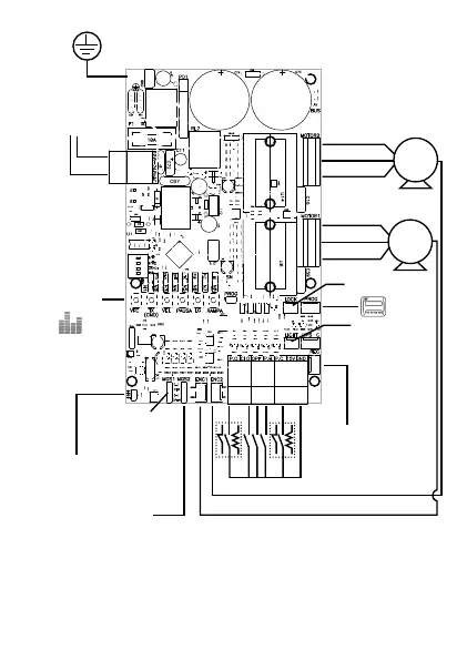
GROUNDING
100 V - 230 V
(50Hz - 60Hz)
POWER SUPPLY
PROGRAMMING
BUTTONS
ANALOG LIMIT
SWITCH REED
(MASTER MOTOR)
OPTIONAL
'ALCANCE'
RECEIVER
(OPTIONAL)
COURTESY LIGHT
PROG
(OPTIONAL) LOCK
INDUCTION MOTOR
(SLAVE)
M
M
INDUCTION MOTOR
(MASTER)
RECEIVER JUMPER
CLOSED = ENABLES RF
OPEN = DISABLES RF
ANALOG LIMIT SWITCH
REED (SLAVE MOTOR)
ENCODER CABLE (MOTOR 1)
ENCODER CABLE (MOTOR 2)
TA
Figure 1
2.4 – CONNECTING THE “ENC1” AND "ENC2" ENCODERS
It is used to connect the encoder, by using a proper cable, between the motor
and the control unit. Inside the operator gearbox there are sensors that pro-
vide the unit control with information about the movement direction and the
position of the gate during the operation. Such information is essential for the
automator's proper operation.
 Loading...