Do you have a question about the PPI neuro 100 and is the answer not in the manual?
Details the initial power-on sequence and display indications.
Explains the primary operating mode showing Process Value (PV) and units.
Describes how alarm conditions are displayed on the Lower Readout.
Introduces parameters accessible via the Operator Page for frequent settings.
Provides a step-by-step guide to navigate and change operator parameters.
Explains how to enter and navigate the indicator's setup mode.
Selects the input sensor type (Thermocouple, RTD, DC Linear).
Explains jumper settings on the CPU PCB for input configuration.
Details how to mount output and option plug-in modules.
Provides specifications for panel cutout and mounting spacing.
Step-by-step instructions for mounting the indicator onto a panel.
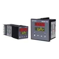
Describes the Upper and Lower LED displays for process values and units.
Explains the function of AL1 and AL2 LED indicators for alarm status.
Details the four tactile keys used for configuration and operation.
Explains jumper settings for input configuration.
Details jumper settings for configuring Output-1 type (Relay, SSR, DC Linear).
Describes output modules and their Relay/SSR jumper settings.
Shows the rear panel terminal layout and wiring connections.
Details connections for AC or DC power supply.
Explains connections for RS485 serial communication with a host.
| Operating System | Android |
|---|---|
| RAM | 2GB |
| Storage | 16GB |
| Connectivity | Wi-Fi, Bluetooth |
| Display Size | 10.1 inches |
| Resolution | 1280 x 800 |
| Processor | Quad Core |