User Manual
ScanLog 96 Pen Drive Version
29
POWER SUPPLY
As standard, the module is supplied with power
connections suited for 85 to 264 VAC line supply. Use well-
insulated copper conductor wire of the size not smaller
than 0.5mm² for power supply connections ensuring proper
polarity as shown in Figure 13.5. The module is not
provided with fuse and power switch. If necessary, mount
them separately. Use a time lag fuse rated 1A @ 240 VAC.
SERIAL COMMUNICATION PORT
Not used. Do not make any connections.
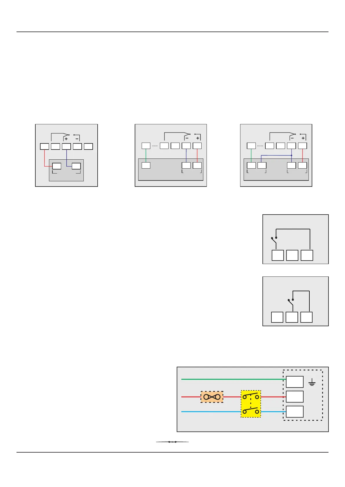
DC EXCITATION VOLTAGE
The ScanLog 4is optionally supplied with 24 VDC @ 0 mA or 5VDC @ 15 mA power source. This is primarily meant for exciting
2-wire or 4-wire Current / Voltage output transmitters.
For wiring convenience the excitation voltage is made available on two separate terminals (15 & 22). The following figures
illustrate a few connection examples for channel 1.
2-wire Current Transmitter
(24VDC Supply)
19
18171615
24V
mA
-+
4 to 20mA
Output
3-wire Voltage Transmitter
(5VDC Supply)
+
Supply
-
1 to 3.6 V
Output
+
21
2019
V
15
5V
18
4-wire Voltage Transmitter
(5VDC Supply)
-
1 to 3.6 V
Output
+
21
2019
V
15
5V
18
+
Supply
-
DIGITAL INPUT FOR BATCH START COMMAND
Connect a remote potential-free contact closure switch for the purpose of issuing the Batch -
Recording START command. An ‘OPEN’ to ‘CLOSE’ change-over of the contacts initiates time
based batch recording. Once the recording starts, the change in the contact status has no effect.
DIGITAL INPUT FOR ALARM ACKNOWLEDGE
Connect a remote potential-free contact closure switch for the purpose of issuing Alarm
Acknowledgment. An ‘OPEN’ to ‘CLOSE’ change-over of the contacts acknowledges the alarm
and mutes the alarm relay(s)
Figure 13.4 (a)
98
Batch
Start
10
Common
Figure 13.5
2 Pole
Isolating Switch
Power Supply Terminals
Earth
Line
Neutral
Fuse
L
N
2
3
1
98 10
Alarm
ACK
Common
Figure 13.4 (b)