Do you have a question about the PRACTIXX PX-KZS-305PA and is the answer not in the manual?
This device is a Sliding Cross-Cut Mitre Saw, designed for cutting wood and plastic materials according to its size. It is not suitable for cutting firewood.
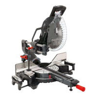
The saw is equipped with a movable saw blade guard (5) that protects against accidental contact with the saw blade and flying chips. This guard automatically releases the saw blade when swung down for a cut and covers it when the saw head is returned to its initial position.
The machine head (4) can be tilted up to 45° to the left and right by loosening the locking screw (22) and pulling out the safety bolt for swiveling function (36). The rotary table (14) can be adjusted for angled cuts by loosening the handle/set screw (11), pressing the indexed position lever (35), rotating the table to the desired angle on the scale (13) using the pointer (12), and then re-tightening the handle.
For repeated cuts of the same length, the longitudinal stop (37) can be opened and used on either the right or left side. The clamping device (7) can be attached to both sides of the fixed saw table (15) to secure the workpiece.
The saw features a cutting depth limiting screw (24) with a knurled nut (24a), allowing for continuous adjustment of the cutting depth for grooving. A laser (32), activated by its ON/OFF switch (33), projects a line onto the workpiece to indicate the exact cutting path.
Dust collection is managed by a dust bag (17) attached to the motor area's outlet opening, which can be emptied via a zipper. An external dust extraction system can also be connected.
The workpiece must have a minimum height of 3 mm and a minimum width of 10 mm, and must always be secured with the clamping device.
Laser Operation (9.1): The laser can be switched on and off with its dedicated button (33). The projected laser line helps guide precise cuts.
Cutting Depth Restriction (9.2): The cutting depth for grooving can be adjusted continuously using the screw (24) and knurled nut (24a). It is crucial to avoid lateral pressure on the saw blade during grooving to prevent kick-back.
Serial Cutting (9.3): For repetitive cuts of the same length, the longitudinal stop (37) can be raised, and the workpiece support (8) adjusted to the desired dimension between the saw blade and the stop.
Chop Cut 90° and Rotary Table 0° (9.4): For cutting widths up to approximately 90 mm, the traction function can be fixed in the rear position using the set screw (20), allowing for chop cutting. For wider cuts, the set screw (20) must be loose, and the machine head (4) movable. The moveable stop rails (16a) should be fixed in the inner position for 90° chop cuts.
Mitre Cut 0°-45° and Rotary Table 0° (9.6): This allows for angled cuts to the left of the work surface. The moveable stop rails (16a) should be fixed in the outer position for these cuts.
Double Mitre Cut 0°-45° and Rotary Table 0°-45° (9.7): This enables simultaneous angled cuts to the left of the work surface and to the stop rail. The moveable stop rails (16a) should be fixed in the outer position.
General Maintenance (10.1): Regularly wipe off chips and dust. Oil rotating parts monthly to extend tool life, but do not oil the motor. Avoid corrosive agents for cleaning plastic.
Cleaning the Movable Saw Blade Guard (10.2): Before each use, check the saw blade guard (5) for dirt and remove any old shavings or wood splinters with a brush or similar tool.
Replacing the Table Insert (10.3): If the table insert (10) is damaged, it must be replaced immediately to prevent small objects from getting stuck and blocking the saw blade. This involves unscrewing the old insert, removing it, inserting a new one, and tightening the screws.
Brush Inspection (10.4): Carbon brushes should be checked after the first 50 operating hours for new machines or new brushes, and every 10 operating hours thereafter. Worn or damaged brushes (length less than 6 mm, burnt spring or shunt wire) must be replaced.
Replacing the Saw Blade (10.5): Always disconnect the mains plug and wear protective gloves. The process involves raising and securing the machine head, lifting the saw blade guard, loosening the flange screw (28) with an Allen key (C) while pressing the sawing shaft lock (30), removing the old blade, cleaning the flanges, and installing the new blade in reverse order. Ensure the saw blade's rotation direction matches the arrow on the housing.
Calibrating the Laser (10.6): If the laser (32) does not show the correct cutting line, it can be readjusted by loosening the screws (32a) and moving the laser sideways until the beam hits the saw blade teeth. The machine must be connected to the mains for laser adjustment, and the ON/OFF switch (2) must not be pressed during this process.
Service Information (10.7): Certain parts like carbon brushes, saw blades, table inserts, and dust bags are subject to natural wear or are considered consumables.