maximum A.V.C.
voltage coincides
with resonance.
An UN-
MODULATED
signal
is
utilized with this
method of align-
ment,
whereas in
the two
previous methods,
a
MODULATED
signal is
employed,
inasmuch
as a
simple
audio
output
meter
•./as
utilized as the
medium
of
resonance
indication.
If a
modulated
signal is
used with this
Method
3,
the audio tone
would merely
serve for the purpose of
audible
signal
identifi-
cation.
SUPERHETERODYNE
RECEIVERS
The superheterodyne
presents
different alignment prob-
lems than those
of the T.R.F.
receiver, though actually none
the more
difficult when
instructions
are
followed and a basic
understanding of the
superheterodyne principle
is
possessed.
Even the
additional features of A.V.C.
(Automatic-Volume-
Control) and A.F.C.
(Automatic-Frequency-Control)
are
easily handled when one acquires a
knowledge of
the
funda-
mental principles.
A
few seconds spent in
roughly reviewing the superhetero-
dyne principle
would
be
in order, at
this moment.
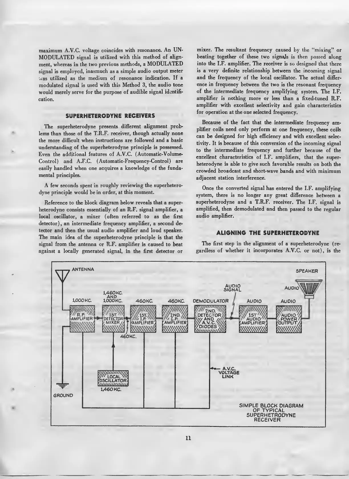
Reference to the block
diagram below reveals that a super-
heterodyne
consists essentially of
an
R.F. signal amplifier,
a
local oscillator,
a
mixer (often referred to as the first
detector),
an intermediate
frequency amplifier,
a second de-
tector and
then the usual audio
amplifier
and loud speaker.
The
main
idea of the superheterodyne principle
is that the
signal from the antenna
or R.F. amplifier
is
caused
to beat
against
a
locally
generated
signal, in the first detector or
mixer.
The resultant frequency caused
by
the "mixing"
or
beating
together of these
two
signals
is then
passed along
into the
I.F. amplifier. The receiver
is so designed that
there
is
a very definite relationship between the
incoming signal
and the frequency
of the local oscillator.
The actual differ-
ence in
frequency
between the two is
the
resonant
frequency
of the
intermediate frequency amplifying
system. The I.F.
amplifier is nothing
more or less than
a fixed-tuned
R.F.
amplifier with
excellent selectivity
and gain
characteristics
for operation
at the one selected frequency.
Because of the fact that
the intermediate
frequency
am-
plifier
coils need
only
perform
at one frequency, these
coils
can be designed for high efficiency
and with excellent selec-
tivity.
It is
because of this
conversion of
the
incoming
signal
to the intermediate frequency and further
because
of the
excellent characteristics
of I.F.
amplifiers, that the
super-
heterodyne is able to give such favorable
results
on both the
crowded broadcast and short-wave
bands and with minimum
adjacent
station
interference.
Once the converted signal
has entered
the I.F. amplifying
system,
there is no longer any
great difference
between
a
superheterodyne
and a T.R.F. receiver.
The I.F.
signal is
amplified, then demodulated and
then
passed to the
regular
audio
amplifier.
ALIGNING THE SUPERHETERODYNE
The first step in the alignment of a superheterodyne
(re-
gardless of
whether it incorporates A.V.C.
or not),
is the
V
ANTENNA
1,000
KC.
R.F
AMPLIFIER
GROUND
SPEAKER
1,460 KC
AND
1,000 KC.
460KC
AUDIO
SIGNAL
460
KC.
1ST.
'//I
DETECTOR
^OSCILLATOR
/////////////////<
460KC.
1,460
KC.
W//////M
2ND.
'
/
'//,
DETECTOR
"
/DIODES 77/
viuuuuttiMlA
0'//
'amplifier'
-
A.V.C.
VOLTAGE
LINK
SIMPLE
BLOCK
DIAGRAM
OF
TYPICAL
SUPERHETRODYNE
RECEIVER
11
 Loading...