GENERAL OPERATING INSTRUCTIONS
Take
note
that this
instrument
has
been designed
for a.c.
operation only,
from any
110-120 volts,
50-60
cycle
source, unless specifically furnished for other
VOLTAGE AND/OR FREQUENCY.
Before using the Signal Generator, it
is
advisable
to
allow the
instrument
to
"warm
up"
for
a
period of at
least
10
minutes. In this manner, all vital components are
given
a chance to
come to
normal operating temperature, insur-
ing the utmost accuracy
and stability of the
output fre-
quency. A
rotary type A.C. Line Switch is on
the "A.V.C.
Control"
located at the
center right-hand side of the in-
strument
panel. A 30 degree
rotation turns
power
"on"
and
leaves the "A.V.C.
Control" ready for use, in zero
volts position.
Immediately set
"RF Control-1", "RF Control-2", and
the
"Modulation
Control" to
their
respective
zero
posi-
tions.
After the
pre-heat period
has elapsed, the
instrument is
ready for
operation.
Procedure at the
receiver end
should
be
in accord
with
manufacturers'
alignment instructions
found in service
manuals
and service notes.
Generalized
alignment procedures
will
be
found
further on
in this
in-
struction
book
and serves
only
as a
guide in the event of
absence of
exact
adjustment notations. Use
of A.V.C. Sub-
stitution is
optional
with the
operator and when not em-
ployed, the
setting of
the "A.V.C.
Control"
in
no way
affects
the
operation of
the instrument
or the alignment pro-
cedure. The
proper use
of A.V.C.
Substitution is
described
under the
generalized
receiver
adjustment
instructions.
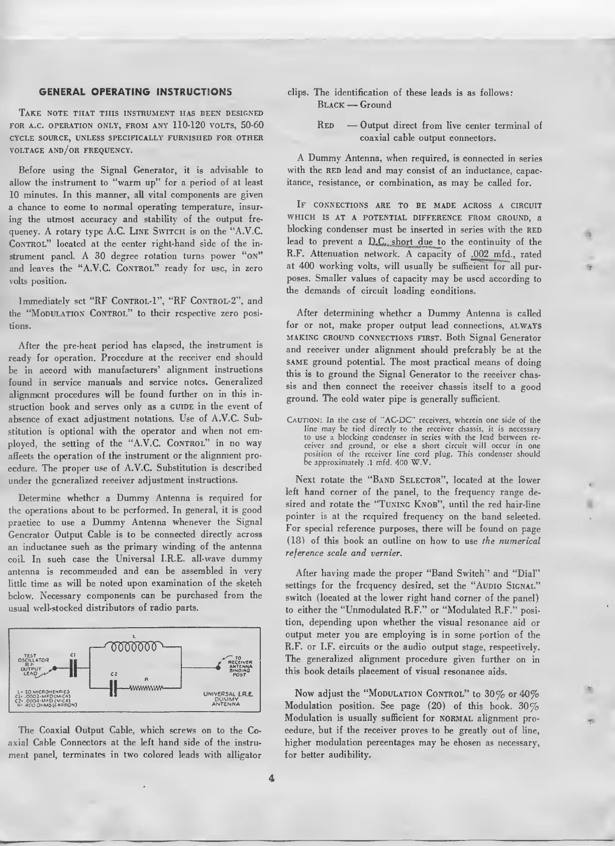
Determine whether
a
Dummy Antenna is required for
the
operations about to be
performed. In
general, it is good
practice to
use a
Dummy Antenna
whenever the Signal
Generator
Output Cable is to be
connected directly across
an
inductance
such as
the primary winding of the antenna
coil. In
such case
the Universal
I.R.E. all-wave dummy
antenna is
recommended
and can be
assembled
in very
little time as
will be
noted upon
examination of the sketch
below.
Necessary
components can be purchased from the
usual
well-stocked
distributors of radio parts.
OLLATO*
OUTPUT
J*
II
LEAD^*^
||
L«
70
MICROHENRIES
CI-
.O0O2-MFDCM'CA)
C7«
00O4-MfD(M'CA)
,
R<
400
0MM5(C*SR0N)
-VWVWvW
RECEIVER
ANTENNA
Binding
POST
universal
i.r.e.
Dummy
ANTENNA
The Coaxial
Output Cable, which
screws on to
the
Co-
axial
Cable
Connectors at the left
hand side of the
instru-
ment
panel, terminates in two colored
leads with alligator
clips.
The identification
of these
leads is as follows:
Black
—
Ground
Red
—
Output direct
from live
center terminal of
coaxial
cable output connectors.
A Dummy
Antenna, when required,
is connected
in series
with
the red lead and
may
consist of an inductance,
capac-
itance,
resistance,
or combination, as may
be called for.
If
connections
are to be made
across a circuit
which
is
at a potential
difference from
ground,
a
blocking
condenser
must be inserted in series with
the
RED
lead
to prevent
a
D^C^^shgrt^due^o the continuity
of the
R.F. Attenuation
network.
A capacity of .002 mf
d.,
rated
at
400 working
volts, will usually
be sufficient for""
all pur-
poses. Smaller values
of capacity may be used according
to
the
demands
of circuit loading
conditions.
After
determining
whether
a Dummy
Antenna
is called
for
or not, make
proper output lead
connections, ALWAYS
making ground
connections
first. Both Signal
Generator
and receiver
under
alignment should preferably
be at the
SAME ground potential.
The
most practical means of
doing
this
is to ground
the Signal
Generator to the receiver
chas-
sis and then
connect
the receiver chassis itself
to a
good
ground. The
cold water
pipe
is
generally sufficient.
Caution: In
the case of "AC-DC" receivers, wherein one side of the
line may be tied directly to the receiver chassis, it is
necessary
to
use a blocking condenser
in series
with
the
lead between
re-
ceiver
and ground, or else a short circuit will occur in
one
position
of the
receiver
line
cord plug.
This
condenser
should
be
approximately
.1
mfd.
400
W.V.
Next
rotate the "Band
Selector", located at the lower
left hand
corner of the panel,
to the
frequency range
de-
sired
and rotate the "Tuning
Knob", until the red
hair-line
pointer is at the required
frequency
on
the band
selected.
For special
reference purposes,
there will be found on
page
(18)
of
this book an outline
on how to use
the
numerical
reference
scale and
vernier.
After having made the
proper "Band Switch"
and "Dial"
settings for
the
frequency
desired,
set the "Audio Signal"
switch
(located at the lower right hand
corner of the
panel)
to either
the
"Unmodulated
R.F." or "Modulated
R.F."
posi-
tion, depending
upon
whether
the visual
resonance
aid or
output meter
you
are employing is
in some
portion of
the
R.F.
or I.F. circuits or the
audio output
stage, respectively.
The generalized alignment
procedure
given
further on
in
this book details placement
of
visual
resonance aids.
Now adjust the
"Modulation
Control"
to
30%
or
40%
Modulation position. See
page
(20)
of this book.
30%
Modulation
is usually sufficient
for normal alignment
pro-
cedure, but
if the receiver
proves
to be greatly out of line,
higher
modulation percentages
may
be
chosen
as necessary,
for better
audibility.
4
 Loading...