To
employ the
"A.V.C.
Substitution" method
merely
examine the receiver
circuit diagram for the location of the
main
A.V.C. voltage lead associated
with the diode detector
and the
A.V.C. load resistor.
Disconnect this lead, as in-
dicated, at the
point
"X", in
the diagram previously re-
ferred to,
and in its place feed the
"A.V.C. Voltage" leads
in proper polarity, as
shown
;
positive
(
•+
)
side to
chassis
or
"ground"
of
receiver
and negative
(
—
)
side
to the
grid
bias returns or (in the
case
of
dual A.V.C.) to the
negative
side of
the
A.V.C; voltage division resistance network. The
direct
reading "A.V.C.
Control"
is
then
set
to the required
voltage.
"What is
this required voltage?" There is no
single accu-
rate answer to this
question, inasmuch as
the actual voltage
developed by
the A.V.C. system
varies with the
receiver
design as well as
with the strength of the
input signal. For
many
receivers, it may
vary (under conditions
of local
sta-
tion
reception) from about 7 to
approximately 25 volts in
accordance with the aforementioned
condition. Under
con-
ditions of no signal
or very small
signal,
the
minimum bias
may be
as
low as one
or two
volts. Hence, you may state
"How am I
to determine where to set the
A.V.C. control?
And if
the
A.V.C.
voltage in
a
receiver can
vary
so
much
under actual
operating conditions, what am I to
gain by
employing
A.V.C.
substitution?" The answer is
very
simple
.
. .
Let us
assume we have
a
receiver wherein the minimum
bias on
the
A.V.C. controlled
stages is about
two
volts.
In
other words, this is
the effective FIXED
bias
on the I.F. and
R.F. stages when no
signal
or only a
very minute
signal is
being received. Now let us
take this same receiver and see
what happens when it
is
being
employed for
the reception
of normal local
broadcast stations,
at
which time
the set
owner desires maximum fidelity.
Under conditions of normal reception, this receiver
may
very well develop 20 volts grid bias in the
A.V.C. circuit,
or
a variation from
small
signal conditions of
20/2.
a ratio
of
10 to
1. Had the same receiver been adjusted with the A.V.C.
substitution
network set for a fixed
bias of anywhere
from
10
to
20
volts, the
ratio between
the voltage
at which the
receiver was
aligned
(about 15 volts),
and
the
voltage ac-
tually developed under normal conditions
of
reception
(about
8 to
20 volts),
would be exceedingly
small. So we
can
readily
see
that it is
not
so
important
to have
an
EXACT
fixed voltage substituted
for the
receiver
A.V.C.
network, but
rather merely
a voltage
SOMEWHERE NEAR
th»
grimily
A*.
veloped A.V.C.
voltage,
It
is therefore not
necessary, as
well
as being
practically
impossible, to present
"A.V.C. Control" setting
data, indi-
vidual
to
all receivers. The
classifications and
settings given
are
therefore quite arbitrary,
but
as just
previously
dis-
cussed,
need not be more
than this.
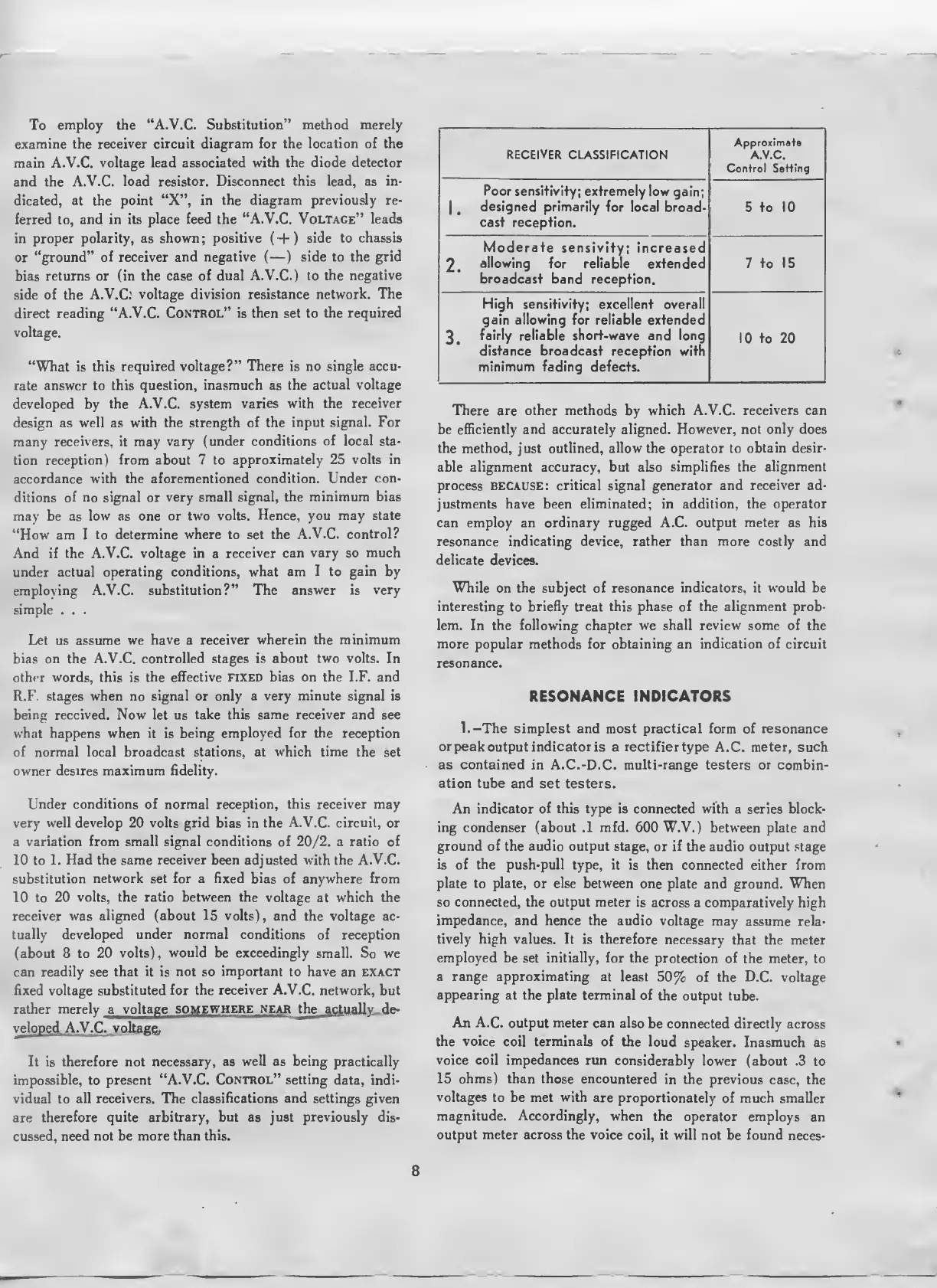
RECEIVER
CLASSIFICATION
Approximate
A.V.C.
Control Setting
Poor sensitivity; extremely
low gain;
|
,
designed
primarily
for local broad-
cast reception.
5 to 10
Moderate
sensivity;
increased
2.
allowing
for reliable
extended
broadcast
band reception.
7 to 15
High sensitivity;
excellent
overall
gain allowing
for reliable extended
3.
fairly reliable short-wave and long
distance broadcast
reception with
minimum fading
defects.
10
to 20
There
are
other methods
by
which A.V.C.
receivers
can
be
efficiently and accurately
aligned.
However, not only does
the method, just
outlined, allow
the operator to
obtain desir-
able alignment
accuracy,
but also
simplifies the alignment
process BECAUSE: critical signal generator and
receiver
ad-
justments have been
eliminated;
in
addition, the operator
can employ an ordinary rugged A.C.
output meter
as
his
resonance
indicating
device,
rather than more costly
and
delicate
devices.
While
on
the subject
of
resonance indicators, it would be
interesting
to
briefly
treat
this phase of the alignment prob-
lem.
In
the following
chapter
we shall review some
of the
more popular methods for obtaining an
indication
of circuit
resonance.
RESONANCE INDICATORS
1.—The simplest and most practical form of resonance
or
peak
output
indicator
is a
rectifier
type
A.C.
meter, such
as contained
in A.C.-D.C.
multi-range
testers
or
combin-
ation tube and
set
testers.
An indicator of this type
is
connected with
a series
block-
ing condenser (about .1 mfd.
600
W.V.)
between plate and
ground of the audio output stage,
or
if
the audio output stage
is of the
push-pull type, it is then
connected either
from
plate to
plate, or
else between
one plate
and
ground.
When
so connected, the output meter is
across a comparatively
high
impedance,
and hence
the
audio voltage
may assume
rela-
tively high values.
It is therefore
necessary that the
meter
employed be
set
initially, for the
protection
of the meter, to
a range approximating
at least
50%
of the D.C. voltage
appearing at the plate terminal
of the
output tube.
An
A.C.
output meter can also
be connected directly across
the voice
coil
terminals
of the loud
speaker.
Inasmuch as
voice
coil impedances run
considerably
lower (about .3
to
15
ohms) than those
encountered
in the previous
case, the
voltages
to be met
with
are
proportionately
of much smaller
magnitude. Accordingly,
when
the operator employs
an
output
meter across
the voice
coil, it will not be found
neces-
8
 Loading...