3
Assembly Instructions
Tools Required for Assembly
Minimum
(2) 1/2” Wrenches
(2) 7/16” Wrenches
Remove from Carton
Remove all parts and hardware packages from the carton.
Assembly
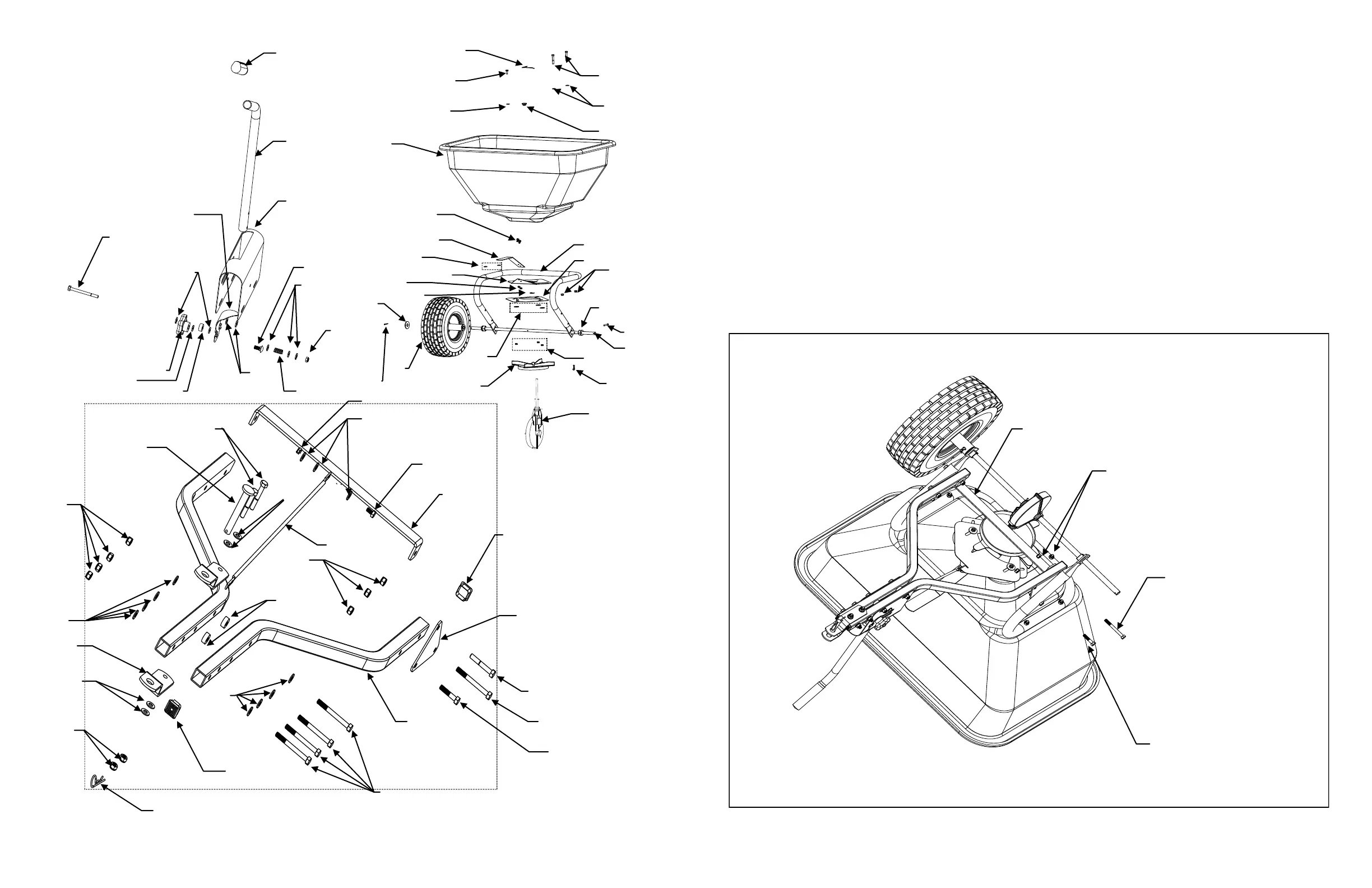
Note: Bolts on the Hitch Arm Assembly are not fully tightened to make assembly easier.
1. Remove two pre-attached 5/16” x 2” Hex Head Bolts in front holes and the two 5/16” x 3” Hex Head Bolts
in rear holes. Remove the 5/16” Nylock Nuts (both sides) and Cross Brace. It is not necessary to remove the
tire for this step, this is shown only for clarity. See Figure 1.
Figure 1
5/16” x 3” Hex Head
Bolt
5/16” x 2”
Hex Head
Bolt
5/16” Nylock Nut
Cross
Brace