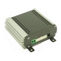
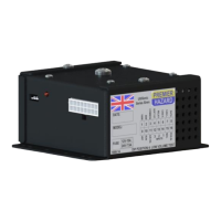
EasyManua.ls Logo

Premier Hazard ShockWave 9005 User Manual

Premier Hazard ShockWave 9005
20 pages
To Next Page IconTo Next Page
Page #1 background imageLoading...
Page #1 background image
ShockWave
9005 Remote Mount Siren Amplifier
General Installation Instructions
Features Overview:
Personal Announce Radio Rebroadcast channel 1
30 Seconds Play / Record Radio Rebroadcast channel 2
60W/100W/200W outputs Multiple Siren Tones
Horn Ring Transfer of tones HRT polarity detection
Run Interlock
Air-horn Input sidelights
Ignition Input Negative inputs
Data logger output Relay output for beacon control
Relay output for horn by-pass CANBUS communication
Digital Audio Amplifier Digital sound reproduction
Robust Construction Circuit protection
Full backward compatibility with 8000 Series siren amplifier controllers
Approvals:
EMC: ECE REG 10.4, E11 10R-04 8014 NPIA specification 5 (issue 11)
Acoustic: KBA, W 25055
As part of our policy of continuous improvement we reserve the right to change
specifications without notice.
WARNIN
G THE
WORLD®
Emergency Service
and Utility Warning
Systems
www.premierhazard.co.uk
WARNING THE WORLD®
Emergency Service and Utility Warning Systems
Premier Hazard Ltd., YO16 4SJ, http://www.premierhazard.co.uk,
Tel.: +44(0)113 239 1111, E-Mail: info@premierhazard.co.uk
© 2013 Premier Hazard ltd. A member of the Public Safety Equipment group of companies
D00217-00-A
REL: 39983

Questions and Answers:

Premier Hazard ShockWave 9005 Specifications

General IconGeneral
BrandPremier Hazard
ModelShockWave 9005
CategoryAmplifier
LanguageEnglish

Summary

General Installation Instructions

Electrical Information

Details operating voltage, speaker requirements, input/output specifications, and temperature range.

Fitting Information

Provides guidance on airflow, wiring placement, and suitable location for the siren amplifier.

In The Box

Lists the components included with the 9005 siren amplifier package.

Product Description

Explains the 9005 siren amplifier's modular design and connectivity with various controllers via CANBUS.

Wiring Loom and Wire Size Selection

Details pin assignments, wire colours, functions, and provides a matrix for selecting wire size based on current and distance.

Key Features and Inputs

Explains the function of Ignition, Run, and Interlock inputs, and details speaker output configurations.

Siren Operation Features

Covers day/night volume control, horn ring transfer, footswitch, and data output functions.

Advanced Outputs and Inputs

Describes relay outputs for horn bypass/beacon control, sidelights input, and Personal Announce (PA) functionality.

Audio and Rebroadcast Functions

Details record/playback, volume control, and operation of Radio Rebroadcast channels 1 and 2.

Fault Detection and Circuit Protection

Explains the fault LED indicators and the siren's protective circuitry against various faults.

Typical Installation Diagrams

Provides diagrams illustrating typical wiring for STC/MTC, 8006, 8007, and CP2 Phase II controllers.

Operational Descriptions

Outlines brief operational use for STC, 8006, 8007, and CP2 Phase II controllers and their respective functions.

Troubleshooting Guide

No Siren Tone Output Issues

Covers checks for no sound output, including controller, power, ignition, fuse, speaker, and input connections.

Fuse Blowing, Voltage, and Current Faults

Addresses fuse blowing, overheating, under/over voltage, and over current faults with relevant checks and solutions.

9005 Siren Amplifier Accessories

Controllers, Microphones, and Wiring Harnesses

Lists various compatible controllers, microphones, and the specific wiring harness for the 9005 siren amplifier.

Speakers, Horns, and Speaker Cowls

Presents available speaker models, horn/flute options, and different types of speaker cowls.

Related product manuals