39
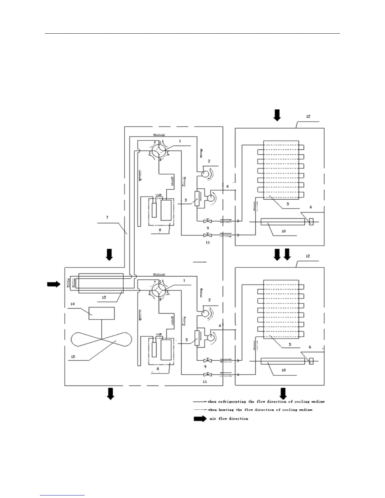
Section 7 Cooling Cycle Diagram
The following chart shows the schematic circuit of the heat pump model. Only cooling only
applies the cooling process(without four way valve)
Cooling Cycle Diagram
1 four
way valve 2 capillary tube 3 single way valve 4 aux-capillary tube 5 evaporator
6 indoor unit motor 7 outdoor unit 8 compressor 9 liquid valve 10 through flow fan
11 gas valve 12 indoor unit 13 condenser 14 outdoor motor 15 axial flow fan