Pressure Systems, Inc. 9016 Upgrade Instructions
www.PressureSystems.com6
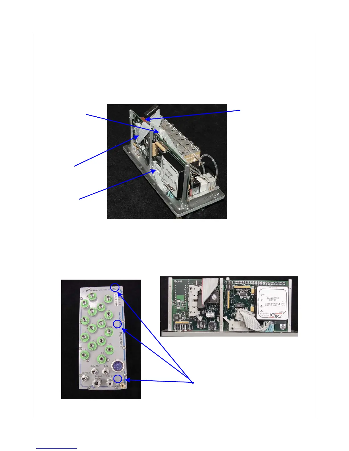
Connector P6
Figure 6
PC-280 Board and Connectors
Tie-wrap to cut
Connector P3
Connector P1
Figure 6a
9016 Top Plate
Figure 6b
PC-280 Board
Three screws to
remove PC-280 board
PC-280 Ethernet Microprocessor/A-D Board
The following procedures should be used for removal of the PC-280 Ethernet Microprocessor/A-D
Board. Use the tools and follow the general warnings already described.
(1) Carefully remove any attached wiring harnesses from connectors P1, P3, and P6 of the PC-
280 board. This will require cutting one nylon tie-wrap attached to the center mounting
bracket. (See Figure 6)
(2) Remove the three (3) 2-56 Phillips head screws securing the PC-280 mounting brackets to
the top plate. These screws will be in line with the PC-280 LEDs that protrude through the
top plate. Save for later use. Carefully lift the board out of the top panel. (See Figures 6a
and 6b.)