SPARES
In order to ensure that the Model P404 thermostatic mixing valve continues to provide satisfactory
service, only GENUINE Pegler spare parts must be used.
Spare part order code Description
A 854453 Protective cap complete with screw
B 854447 Hexagon key
C 854454 Service kit
D 854449 (15mm), 854450 (22mm) Tailpiece Strainer kit
E 854451 (15mm), 854452 (22mm) Angle valve strainer kit
F 854456 (15mm), 854457 (22mm) Sealing washer
G 854455 (15mm), 817012 (22mm) Wafer Strainer
• Carefully remove the element and valve assembly and put to one side.
•
Remove the main spring and flow guide and carefully put to one side.
•
Inspect the components for contamination or damage.
•
Clean or replace as necessary
•
Remove the two o rings
•
Clean the valve body and headwork using a propriety de-scaler
•
Thoroughly rinse the body and headwork in clean water.
•
Carefully fit new o rings from the service kit taking care to ensure they are not
damaged and are correctly located.
•
Lubricate the o rings with the lubricant provided.
•
Re-fit the flow guide and spring lubricating the flow guide around the greatest
diameter with the lubricant provided
•
Lubricate the shuttle valve with the lubricant provided
•
Re-fit the shuttle valve and element assembly.
•
Re-fit the headwork ensuring correct tightening
•
Re-fit the valve assembly
•
If after cleaning the valve, and replacing the o ring seals, the valve does not function
correctly, it may be necessary to replace the thermal element.
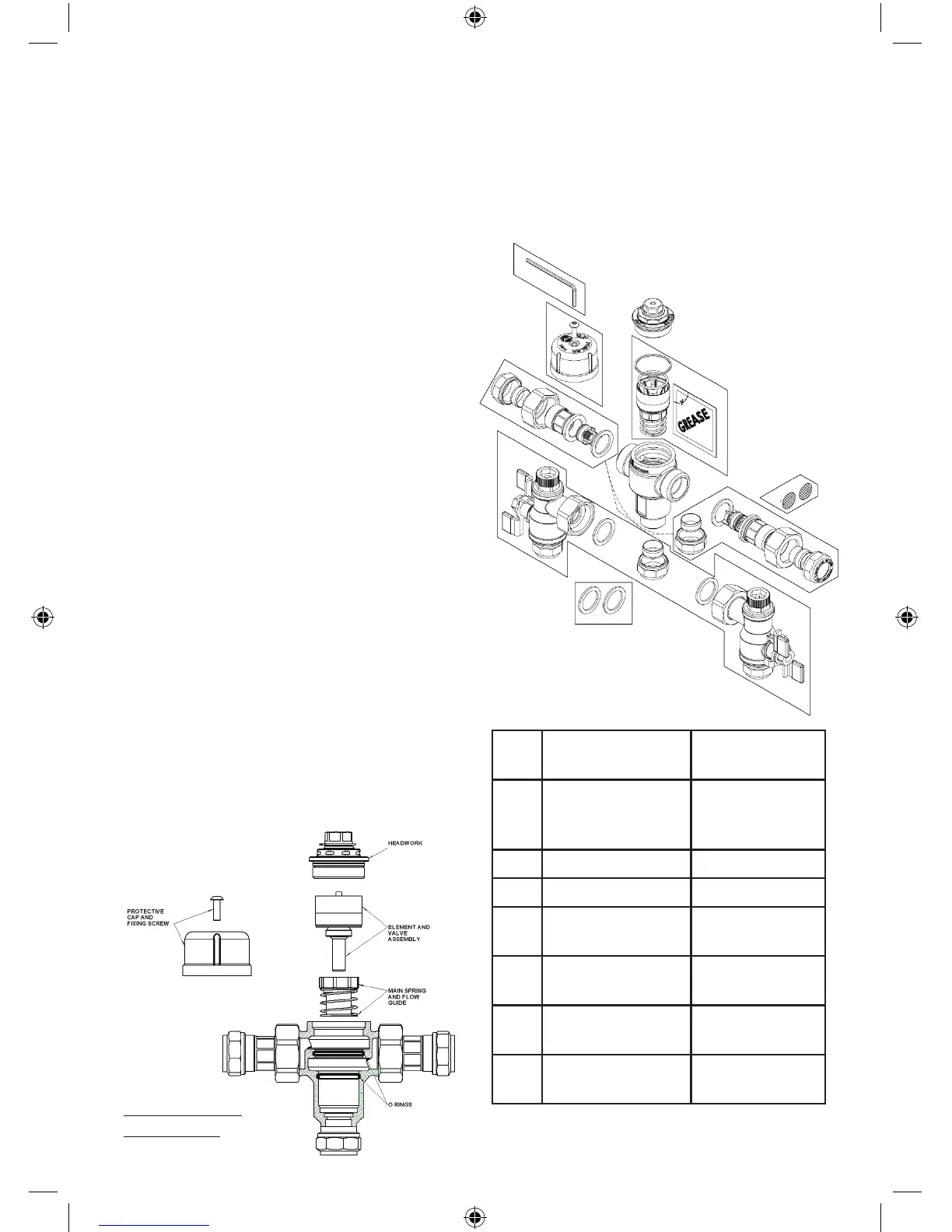
Exploded view of TMV assembly
Exploded view of
TMV assembly
SPARES
In order to ensure that the Prestex Model P404
thermostatic mixing valve continues to provide
satisfactoryservice,onlyGENUINEPeglerspare
parts must be used.
Spare part order
code
Description
1 854453 Protective cap
complete with
screw
2 854447 Hexagon key
3 854454 Service kit
4 854449 (15mm)
854450 (22mm)
Tailpiece
Strainer kit
5 854451 (15mm)
854452 (22mm)
Angle valve
strainer kit
6 854456 (15mm),
854457 (22mm)
Sealing washer
7 854455 (15mm),
817012 (22mm)
Wafer Strainer
1
2
3
4
5
6
4
7
TO SERVICE THE VALVE:
• Isolatethehotandcoldsupply.
• Removethevalvetoacleanworkingarea.
• Removetheprotectivecap.
• Unscrewtheheadworkofthevalve.
• Carefullyremovetheelementandvalve
assembly and put to one side.
• Removethemainspringandowguideand
carefully put to one side.
• Inspectthecomponentsforcontamination
or damage.
• Cleanorreplaceasnecessary
• Removethetwoorings
• Cleanthevalvebodyandheadworkusinga
propriety de-scaler
• Thoroughlyrinsethebodyandheadworkin
clean water.
• Carefullytneworingsfromtheservicekit
taking care to ensure they are not damaged
and are correctly located.
• Lubricatetheoringswiththelubricant
provided.
• Re-ttheowguideandspringlubricating
the flow guide around the greatest diameter
with the lubricant provided
• Lubricatetheshuttlevalvewiththe
lubricant provided
• Re-ttheshuttlevalveandelement
assembly.
• Re-ttheheadworkensuringcorrect
tightening
• Re-ttheassembledvalveandperformthe
comissioning sequence.
• Ifaftercleaningthevalve,andreplacingthe
o ring seals, the valve does not function
correctly, it may be necessary to replace the
thermal element.
TMV3 Model P404.indd 7 13/2/09 15:02:47
 Loading...