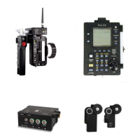
The FI+Z Lens Control System, Rev 1.0, offers high-resolution position and velocity control for camera lenses. The system's core components include a Hand Unit, Motor Driver (MDR2), and Digital Motors. For wireless operation, a Microwave Link 2 can be added, enabling complete control of all functions. An optional F/X unit extends functionality with camera speed ramps, iris, and/or shutter compensation, and provides real-time reporting of camera speed, shutter angle, and footage status.
Hand Unit
The Hand Unit digitizes focus, iris, and zoom commands with 16-bit resolution (1 part in 65,536). This data is transmitted to the 3-Channel Motor Driver via a cable (using RS422 protocol for reliable transmission over distances up to 1 km) or wirelessly through the Microwave Link 2.
- Power: The Hand Unit can be powered via the Command cable in wired mode or by an NMH battery pack in wireless mode. It operates within an input voltage range of 10.5 – 30 VDC.
- Controls:
- Focus Disc and Knob: A large silicone-damped focus knob provides precise control.
- Iris Slider: An iris slider is positioned for one-hand operation.
- Zoom Bargraph: A bright LED bargraph indicates zoom position, remaining off until the Zoom Button on the Micro Force is pressed to conserve battery power. The bargraph is disabled in Snorkel mode.
- Set/Reset Switches: These switches allow operators to quickly adjust the scale relationship between control knob movement and motor rotation, effectively expanding the lens scale and setting end limits. Pressing the switch(es) into the "reset" position instantly restores full-scale operation.
- Zoom Calibration Switch: Momentarily pressing this button cancels any zoom offset, preventing "creep."
- Camera Run Switch: A push-button switch controls camera run/stop functions, activating either momentary pulses (for Arri 24V, Sony video cameras) or constant control voltage (for Panavision, Aaton, Arri 12V cameras). When active, the normally green LED flashes red. The Camera Run function can also be activated by a three-position switch on the Micro Force control, which overrides the Hand Unit's push-button.
- Normal/Snorkel Switch: Located above the Focus knob, this switch enables a special operating mode for driving the Pan and Horizon axes of the Revolution snorkel lens. In Snorkel mode, lens calibration for iris and zoom, and the bargraph display, are disabled. The Micro Force Zoom Control drives both Pan and Horizon axes, maintaining horizon level.
- Remote Iris Receptacle: Located at the bottom of the Hand Unit, this allows an external operator to control iris using the Remote Iris Control (p/n 4020), disabling the Hand Unit's slide control.
- Zoom Mode Switch (on PCB): For driving analog motors in video zoom lenses, the Hand Unit must operate in zoom-velocity mode (switch in "V" position) instead of its default zoom position mode ("P" position). In velocity mode, zoom position information is unavailable, and the bargraph remains dark.
- Ergonomics: Features a replaceable iris scale strip for easy mark placement.
- Zoom Control: Zoom commands are provided by a Micro Force V + F2 or Digital Micro Force zoom control.
Motor Driver 2 (MDR2)
The MDR2 drives up to three motors, provides camera control signals, and transfers camera operating data to the wireless network via the transceiver module.
- Lens Calibration: An automatic lens calibration sequence is initiated when the Reset button is pressed or a motor is connected (if powered). This sequence determines the mechanical limits of the lens's zoom, focus, and iris rings, defining the full travel allowed for precise, repeatable marks and preventing lens or motor damage. Calibrated lens positions are stored in internal memory for 12 hours without external power.
- Motor Protection: Motors are electronically torque-limited, and electronic motor stall protection is provided. Self-resetting thermal fuses protect all three channels, preventing overheating even with improper calibration.
- Direction Reversing Switches: Three-level switches located next to each motor connector allow reversal of motor direction.
- Torque Switches: Three-position slide switches, located below the motor receptacles, adjust the maximum running torque of each motor, which also proportionately changes the calibration torque.
- Camera Control: The "Camera" receptacle provides signals for run/stop, camera speed, and shutter angle control. It also accepts real-time speed, shutter angle, and run/stop status data from the camera, transmitting it to the F/X box via the Microwave Link. This receptacle supports VTR start and internal zoom drive for Sony, Canon, and Fujinon lenses.
- Video Lens Drive: A separate analog command signal is provided to drive video lenses from the Camera output.
- Power: The MDR2 operates over a voltage range of 22 – 30 VDC, requiring a power source capable of 3A current.
- Firmware Updates: Software updates are performed via the "Serial" receptacle using a Serial-PC cable connected to a computer. Updates are available on CD or for download from www.prestoncinema.com.
Digital Motors
Three types of digital motors are used, all employing optical encoders for reliable positional feedback to the MDR unit, free from wear.
- DM-1: A general-purpose motor offering high power output for extended periods. Recommended for stiff lenses in extreme temperatures, vibration, and humidity.
- DM-2: A smaller, lighter motor suitable for most cinema lenses, except the stiffest.
- DM-3: Specifically designed for snorkel lenses, providing high torque and mechanical stiffness for smooth driving of the Pan and Horizon axes of the Revolution Snorkel lens.
- Gears: Motor output gears are 0.80m, available in 0.25" and 0.50" face widths. Step-up gears can be installed over normal output gears for Panavision Zoom (48 DP 20 degree PA), Panavision Iris (64 DP 20 degree PA), Panavision Focus (32 DP, 14.5 degree PA), 0.60m, and 0.70m gears, as well as Canon and Fujinon video lenses.
Microwave Link 2
Operating in the 2.4 GHz band, the Microwave Link 2 uses spread spectrum modulation for a highly reliable link, even with interference. Direct Sequence modulation rejects interfering signals and environmental reflections. It offers 30 transmission channels.
- Components: Includes a Transmitter (for the Hand Unit), Transceiver (for the Motor Driver), an NMH battery pack, a universal fast charger, and antennas.
- Transceiver: Mounts directly on the MDR-2, providing wireless bi-directional communication between the MDR, Hand Unit, F/X unit, and other network clients. It incorporates a voltage booster, enabling MDR operation from 11V to 30V. When operating from 12V, the power source should have 6A current capability for a three-motor installation.
- Battery: The NMH battery pack (12V at 1.5 AH) powers the Transmitter/Hand Unit for 6–8 hours. It includes an internal temperature sensor to protect cells from overcharging or charging below freezing. The Power LED is green during normal operation, flashing red when battery charge is below 10%, and solid red or off when depleted.
- Charger: The Fast Charger (110-240 VAC 50/60 Hz) fully charges a depleted battery pack in 60–80 minutes. The CHARGE LED glows red during fast charge and blinks in trickle mode. The TEMP LED glows if charging outside safe temperature limits (10°C to 50°C).
Installation and Setup
- Motor Coupling: Couple motors to lens gears with minimum backlash, avoiding overtightening or binding. Ensure motor brackets are rigid. Torque adjustment switches can be set to the middle position for normal lenses.
- Camera Connection: Use the appropriate camera cable to connect the MDR2 to the camera accessory receptacle. A special molded "Y" cable (p/n #4510) is required for 24V Arri cameras to control speed and shutter angles.
- Power Connection: Apply 24V – 30 VDC (2A peak typical) via a Power Cable. If the Microwave receiver module is fitted, operation from 11V to 30 VDC is possible.
- Wireless Setup:
- Identify and select an unused operating channel (00-29).
- Plug the Transmitter module into the Hand Unit, ensuring Velcro pads are mated.
- Screw the Transmitter Antenna onto the connector.
- Slide a charged battery into the Transmitter.
- Set Channel Switches on both Transmitter and Transceiver to the same channel.
- Screw the Transceiver antenna into its receptacle, observing polarization labels.
- Switch on power. The Power LED should be green.
- Motor Brackets: Bracket kits provide robust support for industry-standard cameras, ensuring rigidity and lens positioning accuracy.
- 15mm Arri Rod System: Requires an Arriflex Bridge adapter (p/n 4304) for rigid mounting of motors and prevention of rod twisting. A third motor can be installed using a 19mm motor swing arm and a 15mm/19mm adapter bushing. A 19mm rod adapter is provided for use with the Arri handle.
- 19mm Arriflex Rods: Do not require a bridge.
- Panavision Bridge Adapter (p/n 4311): Slides over 0.625" matte box support rods, providing 19mm bushings for mounting motor swing arms. A bushing adapter allows the 19mm swing arm to clamp to the 0.625" rod.
- Lightweight Panavision Bracket (p/n 4341): Secures to the post adjacent to the lens mount, supporting up to two motors with short swing arms.
Maintenance and Troubleshooting
- Motor Overheating: The processor shuts down motor drive if a motor stalls for more than 5 seconds. Reset by removing/re-applying power or unplugging/re-plugging the motor's LEMO connector. Resolve mechanical problems before reconnecting. Allow units to cool if housing temperature exceeds 60°C (140°F).
- Motor Doesn't Turn:
- Check power lights on MDR and Hand Units.
- If motor calibrates, check Hand Unit communication: press Reset switches.
- In wireless mode, verify Transmitter/Transceiver channel settings, correct antennas, and green light on Transmitter (replace battery if not). Ensure Transceiver Cable/Radio switch is in Radio position.
- Try cable mode: remove Transmitter, connect Hand Unit to MDR with command cable, set Transceiver Cable/Radio switch to Cable.
- Motor Rotation Not Smooth:
- Observe motor rotation uncoupled from lens. If smooth, check lens gear for smooth turning and damage.
- If not smooth, substitute motor. If symptom persists, operate in cable mode. If symptom disappears with new motor, send original for service.
- In cable mode, if smooth, check antennas for damage. If roughness decreases with closer Transmitter/MDR distance, problem may be due to bad antenna or damaged Transceiver component.
- Transmitter LED is RED: Replace battery pack with a freshly charged unit.
- Transceiver LED is RED: Supply voltage is < 11.0V. Check for depleted/defective batteries, high internal resistance, or high-resistance power cables. If unit is working normally with red LED, microprocessor contacts may need cleaning (Pro-Gold) by Service Department.
- Lens Doesn't Return to Mark:
- Check motor brackets for flexing during calibration/operation.
- Inspect motor for backlash (< 10mils); return for service if excessive.
- Ensure 15mm motor mounting post is secured.
- Rotate lens gear by hand; check for binding or rough spots.
- No Power to MDR: Check that the proper cable is used and that Arri and Panavision 24V batteries have correct polarities.
- Charge LED Doesn't Come On: Battery may be defective; try another. If LED blinks slowly, fast charge may be delayed until battery voltage or temperature is within safe limits (10°C - 50°C).
- Short Wireless Range: Check antennas for mechanical damage. Ensure Transmitter and Transceiver antennas are not interchanged.
- No Wireless Operation: Verify Transmitter and Transceiver are set to the same channels. Check Transceiver switch is set to Radio. Transmitter LED should be green (check/replace battery if not). Otherwise, return Transmitter and MDR/Transceiver for service.
Power Requirements
- Hand Unit: 11 - 30 VDC input, 80 mA at 12V input.
- Motor Driver (without Microwave Transceiver): 22 - 30 VDC input, 135 mA quiescent current at 24V (without motors). Each motor draws an additional 20 mA for optical encoder power. Peak current requirements: 1.2A for Focus, 0.6-0.9A for Iris/Zoom (at 24V). Maximum driver output is 2A per channel. Ensure power source can supply maximum required current.
- Motor Driver (with Microwave Transceiver): 11 - 30 VDC input. For 12V operation, power source should have 6A current capability (for three motors).
- Calibration and Run Currents:
- IRIS: 650mA/900 mA
- FOCUS: 900 mA/1.2 A
- ZOOM: 800mA/1.2A
The device complies with Part 15 of FCC rules, accepting interference and not causing harmful interference. The FI+Z Microwave Link complies with Class B digital device limits. Troubleshooting steps for interference include reorienting antennas, increasing separation, and consulting a technician. The device also meets Canadian Interference-Causing Equipment Regulations (ICES-003 Issue 2).