Home
PREVOST
Other
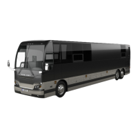
X3-45 COACH
PREVOST X3-45 COACH User Manual
5
of 1
of 1 rating
294 pages
Give review
Manual
Specs
To Next Page
To Next Page
Loading...
OPERA
T
OR’S
MANUAL
X3-45
COACH
2
Table of Contents
Table of Contents
7
Safety Precautions
9
Coach Exterior 2-1
14
Coach Exterior
14
Engine Compartment Components
16
Engine Compartment Curb-Side Door
17
Engine Compartment Rear Door
17
Exhaust Aftertreatment System Access Door
19
Condenser Compartment (A/C)
20
Engine Radiator Door
20
Scr Access Door
20
Evaporator Compartment
21
Coolant Heater
22
Baggage Compartments
23
Front Electrical and Service Compartment
23
Fuel and Diesel Exhaust Fluid (Def) Filler Door
24
Spare Wheel Compartment
24
Entrance Door
26
Door Operation Logic
28
Emergency Entrance Door Opening
28
Rear View Mirrors
28
Wheelchair Lift Access Doors
28
110-120 Volts Connector
30
Back-Up Camera
30
Hubodometer
30
Trailer Hitch
30
Coach Interior 3-1
32
Coach Interior
32
Electronic Destination Sign
33
Steering Wheel Adjustment
33
Utility Compartments
33
Adjustable Hvac Registers
34
Aisle Mirror
34
Driver's Seat - Isri
35
Mechanical Isri Seat
35
Pneumatic Isri Seat
38
Driver's Seat - Ussc 9100Alx
39
Safety Belts
39
Microphone Jacks
40
Passenger Seats
40
Swivel Seats
40
Folding Trays
40
Card Tables
40
Quick-Lounge System
41
Overhead Console
41
Adjustable Air Registers
41
Service Bell
41
Reading Lights
42
Windows
42
Panoramic Windows
42
Driver's Power Window
42
Overhead Compartments
43
Ventilation Hatch
43
Galley
44
Lavatory
44
Waste Container
44
Controls and Instruments 4-1
45
Controls and Instruments
45
Keys
49
E Ntrance Door and Exterior Compartment Doors Key
49
Fuel Filler Door Key (Option)
49
Hand Towel Dispenser Key
49
Lavatory Door Key
49
Utility and Video Compartment Key
49
Utility Compartments Key
49
Ignition Switch
49
Accessories
51
Off
51
Start
51
Other Features
54
Lateral Control Panel
54
C Ontrol Switches (2)
54
C Ruise Control Switch
54
K Neeling / Front Axle Hi-Buoy (Optional)
54
K Neeling / Full Hi-Buoy (Optional)
54
T Ransmission Control Pad (1)
54
Baggage Compartments Locking System
55
H Orn Selector
55
M Irror Controls (Option) (3)
55
Outside Rear View Mirror Heat (Optional)
55
P Ower Window Switch
55
Ashtray (Option) (9
57
C Igarette Lighter (Option) (8)
57
C Oolant Heater Timer (Option) (6)
57
L Ow-Buoy Control Valve (Option) (7)
57
P Arking Brakes Control Valve (5)
57
T Ag Axle Control Valve (4)
57
T Railer Air Supply Control Valve (Option) (12)
57
U Tility Compartment (10)
57
Starting and Stopping Procedure
58
Safety Features and Equipment
58
Automatic Fire Detection and Suppression System (Afss)
58
Back-Up Camera and Monitor
58
Emergency/Parking Brakes Overrule Control Valve
58
Manual Activation Switch
58
On Board Diagnostic Receptacle
58
Protection Panel
58
Scenic Viewing System Camera
58
Controls and Instruments
59
Cruise Control
59
Turning the System on
59
Setting at a Desired Speed
60
Prevost AWARE • Adaptive Cruise Braking
61
Maintaining a Set Following Distance
63
Turning off the ACB System
63
Turning the ACB System on
63
Driver Warnings
65
TPMS Display
69
Operation
70
Dashboard
74
Control Switches
75
H Eadlights and Exterior Lighting
75
L. H. Dashboard Panel
75
H Eadlights Washer
76
T Raction Control System Mud/Snow Mode
78
R. H. Dashboard Panel
80
Cooling Mode Indicator
84
Heating Mode Indicator
84
Hvac Control Unit
84
Fan Speed
85
Driver's Section Temperature Setting
86
Panel
86
Panel and Footwell
86
Passenger's Section Temperature Setting
86
R Ecirculate
86
Windshield Defogger
86
A Udio-Video Selector for the Passenger's Area
87
Temperature Degree Selector
87
Dashboard Radio External Audio Input
93
Dashboard Radio/Mp3/Ipod/CD Player
93
Air Vents
94
Connecting an Ipod
94
Instrument Cluster
95
Analog Indicators
96
C Heck
99
I Nformation
99
S Top
99
T Urn Signal Indicators
99
Telltale Lights
99
A Ftertreatment System Malfunction
100
C Ruise Control
100
C Ruise Control Set Speed
100
D Pf Regeneration Request
100
H Igh Exhaust System Temperature (Hest)
100
P Arking Brake or Emergency Brake Applied
100
A Lternators
101
Controls and Instruments
101
F Lat Tire (with Optional Tire Pressure Monitoring System)
101
H Ill Start Assist
101
Low DEF Level
101
A Ntilock Brake System (Abs)
102
Control
102
H Igh Beam
102
STOP Telltale Light
102
Stop, Check and Information Telltale Lights
102
T Cs/Esc - Traction Control System and Electronic Stability
102
T Railer Antilock Brake System (Abs)
102
Acknowledging Messages
104
CHECK Telltale Light
104
Driver Information Display
104
INFORMATION Telltale Light
104
Scrolling through the Menus Without Using the Steering Wheel Buttons
105
Selecting a Menu
105
To Change Settings
105
Pictograms
107
Pictograms Displayed on the Driver Information Display (DID)
107
Status Line Pictograms
114
C Ourtesy Blinkers (4)
115
H Eadlight Beam Toggle Switch (3)
115
L Ane Change Signal (2)
115
Multi-Function Lever
115
Turn Signal
115
W Indshield Washer Control (5)
115
Steering Wheel Controls
116
Horns
117
Retarder / Engine Brake Low
117
Foot-Operated Controls
118
Operating the Retarder Using the Brake Pedal
118
Operating the Retarder Using the Hand Lever
118
Brake Pedal
119
Accelerator Pedal
120
Allison Transmission
120
Operation
120
Pushbutton Shift Selector
120
P Rimary and Secondary Shift Schedules
121
Transmission Service Indicator
121
Description of Available Ranges
122
N (Neutral)
122
R (Reverse)
122
D (Drive)
123
Second Range)
124
Third and Fourth Ranges)
124
Display
125
Olvo I-Shift Transmission
125
Pushbutton Shift Selector
125
Accelerator Pedal
126
Eco-Roll Mode (Freewheel Function)
126
Economy and Performance Mode
126
Limp Home Mode
126
Starting
127
Starting and Stopping
127
Starting the Vehicle Uphill and Downhill
127
Stopping
127
To Deactivate the Limp Home Mode
127
D Position
128
Driving
128
M Position
128
R Position
129
Towing
129
Other Features 5-1
130
Exhaust Aftertreatment System
132
Filtration and Regeneration Unit
132
Passive Regeneration
132
Active Regeneration
132
Stationary (Parked) Regeneration
132
Initiating a Stationary (Parked) Regeneration
134
Voluntary Interruption of a Stationary Regeneration
135
Other Features
132
Selective Catalytic Reduction Unit
135
Diesel Exhaust Fluid Def
136
Diesel Exhaust Fluid (DEF) Consumption
136
Selective Catalytic Reduction - Driver Warning and Inducement
136
Def Tank Level Driver Warning and Inducement
137
Def Quality Driver Warning and Inducement
138
Scr System Tampering Driver Warning and Inducement
139
Driver Information Display (DID) Menus
140
Fuel Data
140
Gauges
140
Non-Driving/Stationary Mode Menus
140
Prevost Liaison ( Option )
140
Riving Mode Menus
140
Time-Distance
140
Vehicle Messages
140
Display Settings
145
Diagnostics
146
Pre-Trip Assistant (Option)
147
Data Log
149
Aftertreatment
150
Password
151
Transmission Retarder
152
Engine Brake
152
Volvo Engine Brake (Veb)
152
Cruise Control and Engine Brake
154
Antilock Braking System (Abs), Traction Control System (Tcs) & Electronic Stability Control (Esc)
155
Antilock Braking System (Abs)
155
Traction Control System (Tcs)
155
Electronic Stability Control
155
Driver Controlled Differential Lock (Dcdl)
158
Kneeling System
158
Locking the Dcdl
158
Operation Tips
158
Unlocking the Dcdl
158
Low-Buoy
159
Unloading Tag Axle
160
Retractable Tag Axle
160
In-Station Lighting
161
Engine Coolant Heater
161
Switching the Heater on
161
Switching the Heater off
161
Coolant Heater Timer
162
Timer Operating Instructions (Spheros)
162
Viewing the Time (Ignition ON)
162
Troubleshooting and Maintenance
163
Wheelchair Lift System
163
Wheelchair Lift and Access Doors
165
Operating the Wheelchair Lift
165
Adjust Aiming of Acoustic Sensor Beam
166
Adjust Acoustic Sensor Timing
167
Emergency Operation
167
Test Aim of Acoustic Sensor Beam
167
To Manually Deploy the Platform
167
To Manually Lower the Platform
168
To Manually Raise the Platform
168
To Manually Stow the Platform
169
To Manually Stow the Lift from Ground Level
170
Wheelchair Lift Removal for Storing or Maintenance Purposes
170
Wheelchair Lift Installation
172
Interior Appointments
172
Wheelchair Restraint Systems
173
4-Point Securement with Floor Anchorage
173
Wheelchair Occupant Restraint
174
4-Point Securement with Anchorage to Passengers Seat Pedestals
174
Starting and Stopping Procedures 6-1
177
Starting and Stopping Procedures
178
Starting the Engine
178
Starting from the Driver's Seat
178
Stopping the Engine
178
Starting from the Engine Compartment
178
Stopping the Engine
179
Cold Weather Starting
179
Jump Starting
179
Engine Block Heater
183
Engine Protection System
183
Automatic Engine Shutdown
183
Idle Shutdown Timer
183
Engine Warm-Up
184
Allison Transmission Warm-Up
185
I-Shift Transmission - Starting the Vehicle at Low Temperatures
185
Starting the Vehicle after Afire Alarm
185
Safety Features and Equipment 7-1
186
Emergency Exits
187
Side Windows
187
Roof Hatch
187
Safety Features and Equipment
187
Emergency Equipment
191
Fire Suppression System (Afss)
191
Operational Sequence (Fire)
191
System Operation
191
Starting the Vehicle after a Fire Alarm
193
Tire Pressure Monitoring System (Tpms)
194
Description
194
Settings Menu
194
Fire Extinguishers
198
First Aid Kit
199
Fire Hatchet
200
Warning Reflectors
200
Jack / Tools
200
Spare Parts Kit
200
Limp-Home" Belt
200
Lower Alternator Failure
200
Spare Wheel and Tire
201
Changing a Wheel
202
Super Single Tire Replacement
202
Jacking Points
204
Hydraulic Jack
206
Lifting and Towing
206
Tow Eyes as Lifting Point
207
Front Axle as Lifting Point
208
Towing Without Lifting
208
Back-Up Alarm
211
Back-Up Camera
211
Compartment Lighting
211
Daytime Running Lights
211
Fog Lights
211
Mud Flaps and Splash Guards
211
Care and Maintenance 8-1
214
Default Chapter
214
Care and Maintenance
214
Cleaning
216
Seat Upholstery
216
Carpet
217
Exterior Surfaces
217
Floor Cleaning
217
High Pressure Laminate
217
Plastic and Vinyl
217
Rubber Components
217
Stainless Steel
217
Windows
217
Lavatory Maintenance
218
Fresh Water Reservoir
218
Cleaning Cabinet
219
Filling the Sump Tank
219
Draining the Sump Tank
219
Windshield
218
Fluid Level Verification
219
Engine Oil Level
221
Transmission Oil Level
221
Power Steering Fluid Level
223
Cooling Fan Right Angle Gearbox Oil Level
223
Drive Axle Wheel Bearing Oil Level
224
Front and Tag Axle Wheel Hubs
224
Coolant Fluid Level
224
Windshield Washer & Headlights Washer Reservoirs
224
Other Verifications
225
Air Tank Purge
225
Fire Extinguishers
225
Primary Fuel Filter
225
A/C Compressor Belts
226
Fan and Alternator Drive Belts
227
Back-Up Camera
227
Air Filter Restriction Indicator
228
A/C and Heating System Air Filters
229
Hose Inspection
230
Lubrication
230
Wheels and Tires
230
Wheel Bearings
231
Service Brake Test
231
Parking Brake Test
231
Technical Information 9-1
238
Default Chapter
238
Technical Information
238
Capacities
242
Dimensions and Weights
242
Fuel Type
243
Biodiesel Fuels
243
Wheels and Tires
244
Recommended Tire Inflation Pressure at Maximum Cold Load
244
Belts
245
Engine
245
Volvo D13
245
Air System
246
Allison Transmission
246
Antilock Braking System (Abs)
246
Troubleshooting and Testing
246
Automatic Traction Control (Atc) - Electronic Stability Program (Esp)
246
Brakes
246
Brake Chamber Effective Area
246
Propeller Shaft
246
Volvo I-Shift Transmission
246
Electrical System
247
Steering
247
Suspension
247
Drive Axle
247
I-Beam Axle Front Suspension (Option)
247
Independent Front Suspension
247
Tag Axle
247
Alignment Specifications
248
Cooling System
249
Fuel System
249
Exhaust System
250
Heating and Air Conditioning
250
Oil Specifications
251
Allison Transmission
251
Differential
251
Engine
251
I-Shift Transmission
251
Fan Right Angle Gearbox
252
Power Steering Reservoir
252
Pre-Heating System
252
Dot Certification Plate
254
Safety Certification
254
Plates and Certification
254
Abbreviations
257
Appendix A - Service Literature
260
Appendix B - Troubleshooting Guide for Multiplex Vehicles
263
APPENDIX C - Allison Transmission's Other Features 1
275
Allison Transmission 5Th Generation Oil Level Check Using the Pushbutton Shift Selector
275
Control System Prognostics
277
Normal Prognostics Indication at Engine Start
277
Oil Life Monitor
277
Filter Life Monitor
278
Transmission Health Monitor
279
Appendix C - Allison Diagnostic Troubleshooting Codes
281
Diagnostic Troubleshooting Codes (Dtc) - Allison 5Th Generation Controls
281
Diagnostic Code Display and Clearing Procedure
281
Diagnostic Troubleshooting Codes (Dtc) Overview
281
Using Shift Selector for Accessing Diagnostics Information
281
Diagnostic Trouble Code Response
282
Appendix D - Spheros Preheater Flash Codes
291
Appendix E - Tpms Troubleshooting Guide
293
5
Based on 1 rating
Ask a question
Give review
Questions and Answers:
Need help?
Do you have a question about the PREVOST X3-45 COACH and is the answer not in the manual?
Ask a question
PREVOST X3-45 COACH Specifications
General
Engine
Volvo D13
Horsepower
500 hp
Length
45 ft
Width
102 in
Seating Capacity
56 passengers
GVWR
54, 000 lbs
Transmission
Allison B500
Related product manuals
PREVOST X3-45 COACH 2018
227 pages
PREVOST X3-45 Commuter 2020
228 pages
PREVOST X3-45
161 pages
PREVOST X3-45 2016
459 pages
PREVOST X3-45 VIP 2015
190 pages
PREVOST X3-45 VIP 2017
212 pages
LE MIRAGE XLII BUS SHELLS
1342 pages