Jazzy EVO Series www.pridemobility.com 31
VII. CARE AND MAINTENANCE
Wheel Replacement
If you have pneumatic tires and you have a at tire, replace the tube. If your chair is equipped with a solid tire
insert, then you must replace the whole wheel assembly. Replacement tires, tubes, and wheel assemblies are
readily available through your authorized Pride Provider.
WARNING! The wheels on your power chair should only be serviced or replaced by an authorized
Pride Provider or a qualied technician.
WARNING! Be sure that the power to the controller is turned off and the power chair is not in
freewheel mode before performing this procedure.
WARNING! When changing a tire, remove only the center lug nut and washer, then remove the
wheel. If any further disassembly is required, deate the tire completely or it may explode.
Follow these easy steps for a quick and safe repair
for both pneumatic and solid tires:
1. Turn o the power to the controller.
2. Make sure that the power chair is in drive mode.
See gure 5.
3. Raise and support the power base so that the
wheel is at least 1 in. (2.5 cm) o of the ground.
4. If you are changing a pneumatic tire, completely
deate it before removing the wheel.
5. Remove the cap cover, if equipped.
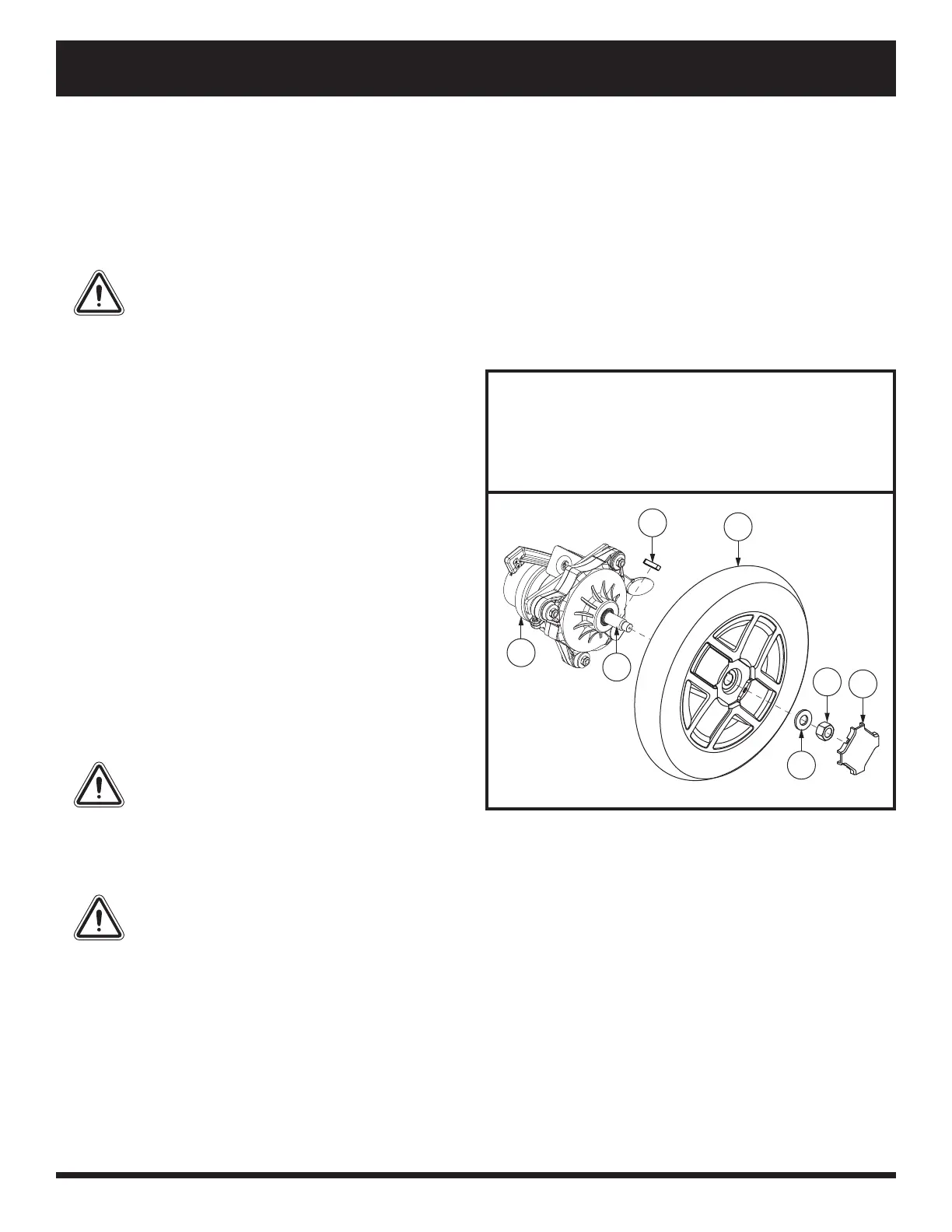
6. Remove the drive wheel nut and washer from the
axle. See gure 18.
7. Remove the drive wheel from the axle. Make sure
that you keep the key.
8. Slide the wheel back onto the axle. Make sure that
the key is in the axle slot.
WARNING! Ensure that the axle key
is properly installed into the axle
slot when mounting the wheel. If not
installed securely, the braking and
drive systems are disengaged which
may cause personal injury or product
damage.
9. Reinstall the drive wheel nut and washer onto the axle and tighten. See gure 16.
WARNING! Make sure both the nut and washer are reinstalled and tightened properly.
10. Reinstall the cap cover, if equipped.
11. Inate the pneumatic tire to the psi/bar/kPa air pressure rating indicated on each tire.
12. Remove the power chair from the base support.
Figure 18. Drive Wheel Removal
1. Motor
2. Key
3. Axle
4. Drive Wheel
5. Drive Wheel Nut
6. Drive Wheel Washer
7. Cap Cover
Identification Key
1
2
4
5
7
6
3
 Loading...