28 www.pridemobility.com Fusion
Controller Position
You can move the controller in toward or out away from the
armrest, or change the position of the controller for either
left-hand or right-hand use.
MANDATORY! Prevent controller harness
damage! Avoid routing the controller
harness on the outside of the armrest pad.
Route the harness under the armrest or
toward the inside of the armrest pad. Use
correct tie-down points for the controller
harness to prevent the harness from getting
caught in the drive tyres, pinched in the
seat frame, or damaged when passing
through doorways.
To change the controller position:
1. Turn off the power to the controller.
2. Unplug the controller connector from the front of the
power base. See figure 6.
3. Remove any wire ties securing the controller harness to
the armrest.
4. Loosen the adjustment knob on the armrest where the
controller is currently located. See figure 23.
5. Loosen the adjustment knob on the armrest where the
controller will be installed. See figure 23.
6. Relocate the controller to the desired armrest and
tighten the adjustment knob to secure the controller.
7. Use wire ties to secure the controller harness to the
armrest.
8. Route the controller harness to the front of the power
base and reconnect the controller. See figure 6.
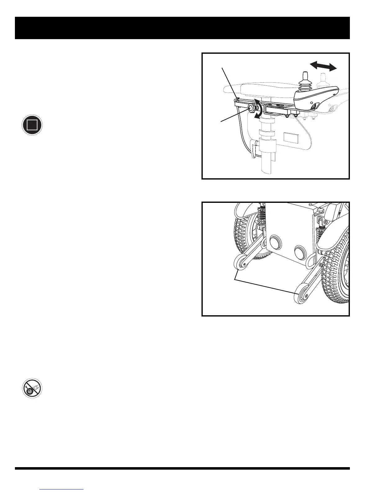
To extend the controller:
1. Loosen the adjustment knob on the armrest.
See figure 23.
2. Slide the controller into or out to the desired position.
3. Tighten the adjustment knob to secure the controller.
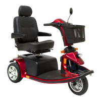
Anti-tip Wheels
The anti-tip wheels are an integral and important safety fea-
ture of your power chair. They are bolted to the frame at the
rear of the power chair. See figure 24.
PROHIBITED! Do not remove the anti-tip
wheels or modify your power chair in any
way that is not authorised by Pride.
IV. COMFORT ADJUSTMENTS
Figure 23. Controller Position
Figure 24. Anti-tip Wheels
ADJUSTMENT
KNOB
SECUREMENT
CLIP