8 www.pridemobility.com Jazzy 614 with Dynamic Electronics Technical Troubleshooting Guide
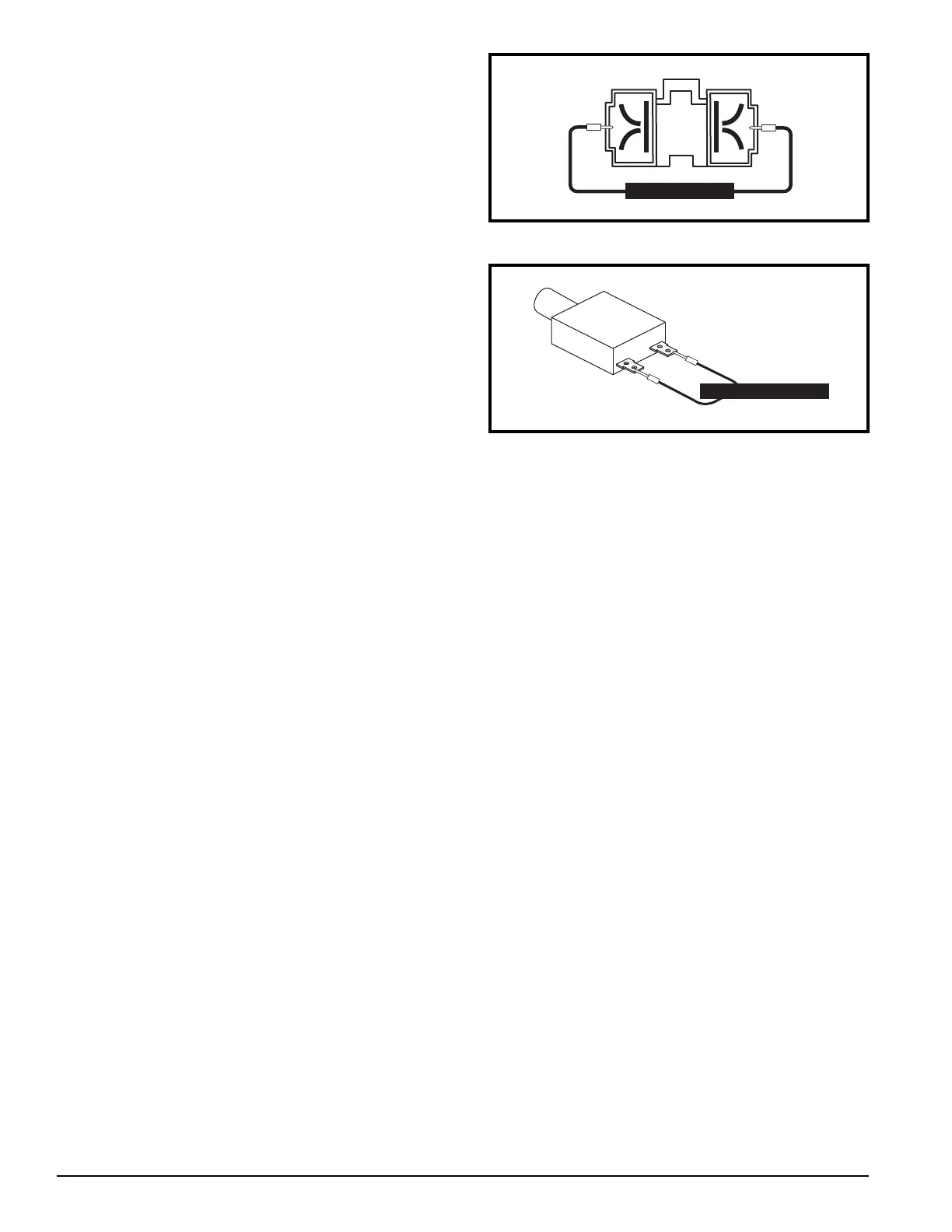
Figure 11. Circuit Breaker (13)
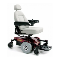
Figure 10. Connector 7a
Measure Res
stance
15. Measure voltage across connector 6b and connector 6c.
See diagram 3.
— If the multimeter indicates 0VDC, then replace both bat-
teries and retest the system.
— If the multimeter indicates greater than 0VDC, then
replace the rear battery harness (6) and retest the system.
From step 14
16. Measure voltage across pin 1 and pin 2 of connector 7a.
See figure 10.
— If the multimeter indicates 0VDC
, then go to the next step.
—
If the multimeter indicates greater than 0VDC,
then go to
step 18
.
17. Measure voltage across connector 7b and connector 7c.
See diagram 3.
— If the multimeter indicates 0VDC, then replace both bat-
teries and retest the system.
— If the multimeter indicates greater than 0VDC, then
replace the front battery harness (7) and retest the system.
From step 16
18. Measure resistance across the two terminals of the cir-
cuit breaker (13). See figure 11.
— If the multimeter indicates about 1 ohm, then replace the
power interface harness (5) and retest the system.
— If the multimeter indicates an open, then replace the cir-
cuit breaker (13) and retest the system.
 Loading...