ASSEMBLY DIAGRAM 8 USE A PARTNER TO HELP WITH THIS STEP
REMEMBER: Only hand tighten all nuts and bolts until whole machine is assembled
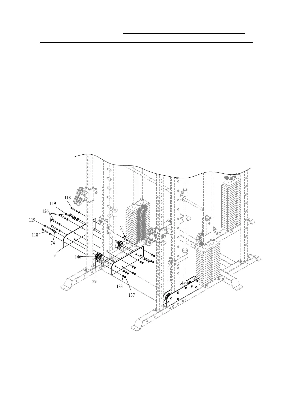
1. (See the pulley exploded diagram for more detail.) Attach BAFFLE (9) to REAR SILIDE FRAME (5)
andRIGHTANDLEFTBASE(1&2)withBOLTM12*85(126),WASHER12(134)andLOCKNUT
M12(138).
2. AttachPULLEY(146)toBAFFLE(9)withNYLO NBUSHING(74),BOLTM10*90(119),WASHER
10(133)andLOCKNUTM10(137).
3. Attach ROUND TUBE (29) to BAFFLE (9) with BOLT M10*85 (118), WASHER 10 (133) and
LOCKNUTM10(137).
4. Attach HOLDER (31) to BAFFLE (9) with BOLT M10*85 (118), WASHER 10 (133) and LOCK
NUTM10(137).
 Loading...