-6-
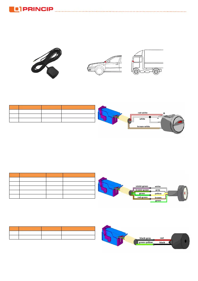
GPS and GSM signals penetrate glass, plastics and other non-conductive materials. The GPS antenna must not be
covered with conductive material in the direction of reception of the signal.
Warning: Some vehicles have metal-plated windscreen. These glasses do not allow electromagnetic wave
propagation. In these cases, use a roof antenna or consult the location of the antenna with the manufacturer. There
are areas without the metallization in some metalized windscreens which can be used for antennas.
5. Installation of optional peripherals
5.1. Business/private journey switch
User can use this switch to select the journey type. If the LED lights up, it is a private journey.
5 white input IN1 LED cathode, swith
4 brown-white ground switch
5.2. DALLAS chip reader (driver identification)
Dallas chip reader is used to identify the driver in the vehicle. When the unit is activated the LED in the center of
the sensor is permanently lit. The driver is identified by attaching the Dallas chip to the reader. The unit records the
chip code and the sensor light goes out. Logging out can be done by reattaching the same chip or turning off the
ignition. The sensor has five wires but only four are used. Usually, select the red light and therefore connect the
brown sensor wire. For green light connect the green wire. Some sensors from other manufacturers may have
different color marking on the wires
pin harness reader signal
24 brown-green grey GND
18 green yellow OUT1, LED cathode
- - green green LED anode
5.3. Buzzer (driver identification)
Acoustic signal for Dallas chip reader. When the unit is activated, the buzzer start to beep for reminding the
driver to use the Dallas chip for identification. The beep signal continues until the chip is attached to the reader.
pin harness buzzer signal
12 black-grey red IGN
 Loading...