DRIVE “JAGUAR REPLACEMENT KIT”
D / 2
WITHOUT OUR CONSENT THE REPRODUCTION OR COMMUNICATION TO THIRD PARTIES IS PROHIBITED BY LAW
ANNEXE “A”
SUBJECT TO CHANGE WITHOUT NOTICE
Connection
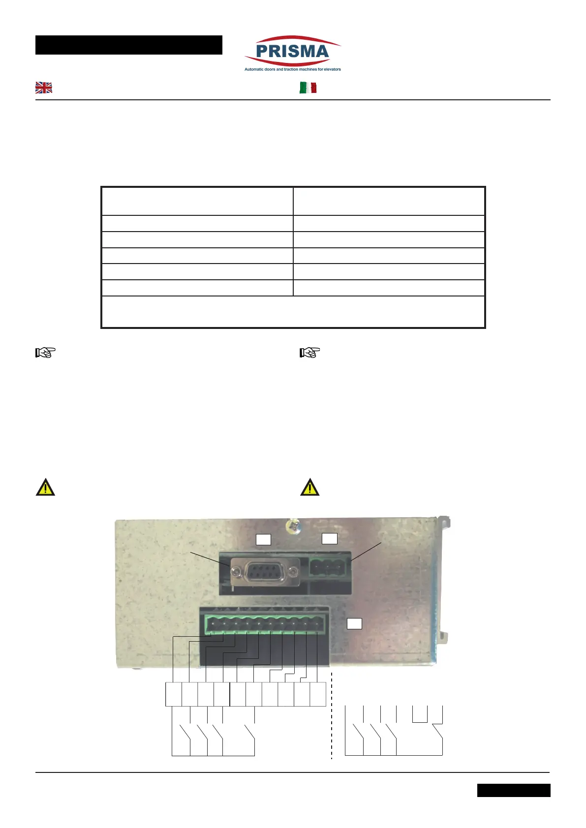
• If they are not connected yet, connect the motor power
supply connector X1 and the X2 connector of the
encoder after having grounded the system as shown
in the prior image.
• Connect the 230 V mains power and turn the switch (1)
as indicated in the following picture.
• Verify that the RIGHT - LEFT or CENTRE CLOSING set-
ting of the door is correct:
- Setup of the closing direction is performed in the factory
prior to delivery, for this reason this paragraph is only informa-
tional.
The following pictures show the wiring of the drive.
The connection between the motor and the terminal board of the
drive is performed in the factory according to the closing side of
the door, as shown in detail.
If the wiring is faulty (wrong closing direction) the drive will not
be able to distinguish opening and closing direction of the door
correctly.
-The drive must receive all commands from "clean" contacts
i.e. without potential.
12345678910
COMMON
NOT IN USE
USER INTERFACE
PHOTOCELL N.O. PHOTOCELL N.C.
OPEN CLOSE NUDGE PHOTOCELL COMMON OPEN CLOSE PHOTOCELL
BRIDGE
A TERMINE DI LEGGE E’ VIETATA LA RIPRODUZIONE O COMUNICAZIONE A TERZI SENZA NOSTR A APPROVAZIONE
ALLEGATO “A”
SOGGETTO A MODIFICHE SENZA PREAVVISO
31_42_01_01REV03
Collegamento
• Collegare al drive, se non già collegati, il connettore
X1 di alimentazione del motore e il connettore X2
dell’encoder dopo aver collegato l’impianto a terra come
indicatonellapecedentegura.
• Collegare l’alimentazione da rete 230 V e accendere
l’interruttore (1) indicato nella seguente immagine.
• Vericare che il settaggio porta DX-SX o CENTRALE
sia corretto:
- Il settaggio relativo al senso di chiusura è eseguito in fab-
brica prima della consegna, pertanto questo paragrafo ha solo
valore informativo per i drives forniti come ricambi.
Le immagini seguenti illustrano lo schema di cablaggio del drive.
Il collegamento tra il motore e la morsettiera e tra l’encoder e la
stessa morsettiera è eseguito in fabbrica e tiene conto del senso
di chiusura della porta, come indicato nel dettaglio.
L’eventuale inversione del cablaggio relativo al senso di chiusura
della porta fa sì che il drive non distingua il senso di apertura da
quello di chiusura.
- I comandi al drive vanno impartiti mediante contatti “puliti”,
cioè liberi da potenziale.
Right/centre Closing door
Porte con chiusura verso destra/centrale
Left Closing door
Porte con chiusura verso sinistra
C1S/R C1S/L
C2S/R C2S/L
C3S/R C3S/L
C2C
C4C
See following picture for connections
Vedere le connessioni nell'immagine seguente
 Loading...