4
INSTALLATION
MOUNT GRINDER
• Mount grinder to a solid horizontal surface (hardware not pro-
vided). If mounted to metal pedestal, align mounting holes
with corresponding holes in pedestal. Insert a
1
/4-20 x 1¼” hex
head bolt with flat washer through base of grinder. From bot-
tom of pedestal, place a
1
/4” flat washer and
1
/4”-20 hex nut onto
the bolt. Tighten only until space between grinder base and
pedestal is
1
/8” (base should be flush for PR7310). Using second
nut on each bolt, jam tighten against the first to prevent loos-
ening by vibration.
• To mount grinder to wooden bench top, use
1
/4 x 1¼” wood
screws with flat washers beneath heads. Tighten screws until
space between grinder base and bench top is
1
/8” (base should
be flush for PR7310).
GROUNDING INSTRUCTIONS
WARNING: Improper connection of equipment grounding con-
ductor can result in the risk of electrical shock. Equipment should
be grounded while in use to protect operator from electrical shock.
• Check with a qualified electrician if grounding instructions are
not understood or if in doubt as to whether the tool is properly
grounded.
• This grinder is equipped with an approved 3-conductor cord
rated at 300V and a 3-prong, grounding type plug (See Figure
2) for your protection against shock hazards.
• Grounding plug should be plugged directly into a properly
installed and grounded 3- prong grounding-type receptacle
(See Figure 2).
• Do not remove or alter grounding prong in any manner. In the
event of a malfunction or breakdown, grounding provides a
path of least resistance for electrical shock.
WARNING: Do not permit fingers to touch the terminals of plug
when installing or removing from outlet.
• Plug must be plugged into matching outlet that is properly
installed and grounded in accordance with all local codes and
ordinances. Do not modify plug provided. If it will not fit in out-
let, have proper outlet installed by a qualified electrician.
• Inspect tool cords periodically, and, if damaged, have repaired
by an authorized service facility.
• Green (or green and yellow) conductor in cord is the grounding
wire. If repair or replacement of the electric cord or plug is nec-
essary, do not connect the green (or green and yellow) wire to
a live terminal.
• Where a 2-prong wall receptacle is encountered, it must be
replaced with a properly grounded 3-prong receptacle installed
in accordance with National Electric Code and local codes and
ordinances.
WARNING: This work should be performed by a qualified
electrician.
• A temporary 3-prong to 2-prong grounding adapter (See
Figure 3) is available for connecting plugs to a two pole outlet
if it is properly grounded.
• Do not use a 3-prong to 2-prong grounding adapter unless
permitted by local and national codes and ordinances.
(A 3-prong to 2-prong grounding adapter is not permitted in
Canada.) Where permitted, the rigid green tab or terminal on
the side of the adapter must be securely connected to a per-
manent electrical ground such as a properly grounded water
pipe, a properly grounded outlet box or a properly grounded
wire system.
• Many cover plate screws, water pipes and outlet boxes are not
properly grounded. To ensure proper ground, grounding means
must be tested by a qualified electrician.
EXTENSION CORDS
• The use of any extension cord will cause some drop in voltage
and loss of power.
• Wires of the extension cord must be of sufficient size to carry
the current and maintain adequate voltage.
• Running the unit on voltages which are not within ±10% of the
specified voltage may cause overheating and motor burn-out.
• Use the table to determine the minimum wire size (A.W.G.)
extension cord.
• Use only 3-wire extension cords having 3-prong grounding
type plugs and 3-pole receptacles which accept the tool plug.
• If the extension cord is worn, cut or damaged in any way,
replace it immediately.
EXTENSION CORD LENGTH (120 VOLTS)
Model PR736
Wire Size A.W.G.
Up to 25 ft. . . . . . . . . . . . . . . . . . . . . . . . . . . . . . . . . . . . . . . . . . . . . . . . . . . . . .18
25 - 100 ft. . . . . . . . . . . . . . . . . . . . . . . . . . . . . . . . . . . . . . . . . . . . . . . . . . . . . .16
100 - 150 ft. . . . . . . . . . . . . . . . . . . . . . . . . . . . . . . . . . . . . . . . . . . . . . . . . . . . .14
NOTE: Using extension cords over 150 ft. long is not recommended.
EXTENSION CORD LENGTH (120 VOLTS)
Model PR738 and PR7310
Wire Size A.W.G.
Up to 25 ft. . . . . . . . . . . . . . . . . . . . . . . . . . . . . . . . . . . . . . . . . . . . . . . . . . . . . .18
25 - 50 ft. . . . . . . . . . . . . . . . . . . . . . . . . . . . . . . . . . . . . . . . . . . . . . . . . . . . . . .16
50 - 100 ft. . . . . . . . . . . . . . . . . . . . . . . . . . . . . . . . . . . . . . . . . . . . . . . . . . . . . .14
100 - 150 ft. . . . . . . . . . . . . . . . . . . . . . . . . . . . . . . . . . . . . . . . . . . . . . . . . . . . .12
NOTE: Using extension cords over 150 ft. long is not recommended.
EXTENSION CORD LENGTH (240 VOLTS)
Model PR736, PR738 and PR7310
Wire Size A.W.G.
Up to 50 ft. . . . . . . . . . . . . . . . . . . . . . . . . . . . . . . . . . . . . . . . . . . . . . . . . . . . . .18
50 - 200 ft. . . . . . . . . . . . . . . . . . . . . . . . . . . . . . . . . . . . . . . . . . . . . . . . . . . . . .16
200 - 300 ft. . . . . . . . . . . . . . . . . . . . . . . . . . . . . . . . . . . . . . . . . . . . . . . . . . . . .14
100 - 150 ft. . . . . . . . . . . . . . . . . . . . . . . . . . . . . . . . . . . . . . . . . . . . . . . . . . . . .12
NOTE: Using extension cords over 300 ft. long is not recommended.
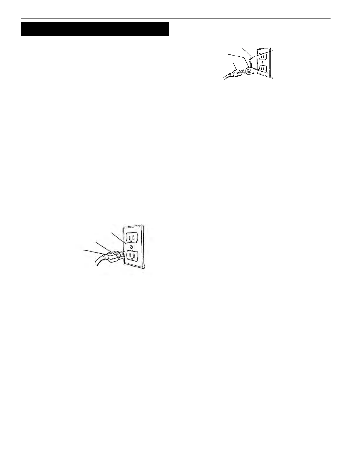
Figure 3 – 2-Prong Receptacle
Grounding Lug
Adapter
3-Prong Plug
2-Prong Receptacle
Make sure this is
Connected to a known
Grounded Receptacle
Figure 2 – 3-Prong Receptacle
Properly Grounded Outlet
Grounding Prong
3-Prong Plug
PR736, PR738 and PR7310
 Loading...