5
INSTALLATION (CONTINUED)
ELECTRICAL CONNECTIONS
WARNING: All electrical connections must be performed by a
qualified electrician. Make sure tool is off and disconnected from
power source while motor is mounted, connected, reconnected or
anytime wiring is inspected.
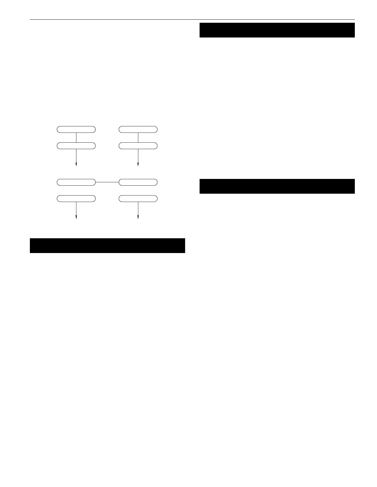
• Motor and wires are installed as shown in wiring diagram (See
Figure 4, page 5). Motor is assembled with approved, 3-conduc-
tor cord to be used at 120/240 volts. Motor is prewired at the
factory for 120 volts.
• To use the grinder with a 240V power supply, have a qualified
electrician rewire motor and attach a 240 volt, I5A three-prong
plug onto grinder line cord.
OPERATION
WARNING: Always wear safety glasses complying with United
States ANSI Z87.1 (shown on package) before commencing power
tool operation.
• Keep a steady, moderate pressure on the work and keep it
moving at an even pace for smooth grinding.
• Pressing too hard overheats the motor and prematurely wears
down the grinding wheels.
• Note the original bevel angle on the item to be sharpened and
try to maintain that angle. Sharpening a cutting edge requires
removing burrs from edge.
• Deburring edge is done best by using the grinder to pull burr
from edge across the bevel angle.
• The grinding wheel should rotate into object being sharpened.
• Dip work into a coolant regularly to prevent overheating.
Overheating can weaken metals.
MAINTENANCE
• As wheels wear, tool rests should be positioned closer to the
face of the wheels.
• The gap between the wheel and the tool rest should not be
greater than
1
/16”. When the wheels are worn to the extent that
the
1
/16” maximum gap cannot be maintained, the wheels
should be replaced.
• Models PR736 and PR738: Replacement wheels should have a
minimum rated speed of at least 3600 RPM.
• Model PR7310: Replacement wheels must have a minimum
rated speed of 1800 RPM.
• Maximum wheel diameter is 6” for PR736, 8” for PR738, and 10”
for PR7310.
• To loosen nuts holding the wheels, disconnect power and push
a wood wedge between the tool rest and the wheel to keep
the shaft from turning. The threads on the right side of the
grinder (facing unit) are right hand; threads on the left side are
left hand. Tighten nuts securely before operating the grinder.
• For grinding efficiency, wheels should be dressed periodically,
especially if they become clogged from grinding soft metals.
WARRANTY
PRM warrants their products to be free of defects in material or
workmanship. This warranty does not cover defects due
directly or indirectly to misuse, abuse, normal wear and tear, failure
to properly maintain the product, heated, ground or otherwise
altered, or used for a purpose other than that for which it was
intended. The warranty does not cover expendable and/or wear
parts (i.e. v-belts, coated screws, abrasives), damage to tools arising
from alteration, abuse or use other than their intended purpose,
packing and freight. The duration of this warranty is expressly lim-
ited to one year parts and labor, unless otherwise noted below
beginning from the date of delivery to the original user.
The obligation of PRM is limited solely to the repair or replace-
ment, at our option, at its factory or authorized repair agent of any
part that should prove deficient. Purchaser must lubricate and
maintain the product under normal operating conditions at all
times. Prior to operation become familiar with product and the
included materials, i.e. warnings, cautions and manuals. Failure to
follow these instructions will void the warranty.
This warranty is the purchaser’s exclusive remedy against PRM for
any deficiency in its products. Under no circumstances is PRM liable
for any direct, indirect, incidental, special or consequential damages
including lost profits in any way related to the use or inability to
use our products. This warranty gives you specific legal rights
which may vary from state to state.
Figure 4 – Wiring Diagram
3-Red 2-Gray
4-Yellow
1-Black
120V
240V
3-Red
1-Black
2-Gray
4-Yellow
PR736, PR738 and PR7310
 Loading...