Do you have a question about the PRO Charging System Industrial Series and is the answer not in the manual?
This document provides installation and operating instructions for the PRO Charging Systems Industrial Series battery chargers. These chargers are designed for permanent installation and are fully automatic.
The PRO Charging Systems Industrial Series battery chargers are designed to charge 12V lead-acid batteries (including sealed lead acid, gel cell, and AGM types) in various configurations. They are waterproof, on-board systems built to withstand intense vibration, extreme temperature variations, and submersion. Each charging bank operates independently, ensuring that multiple batteries are charged simultaneously and to 100% capacity. The chargers incorporate temperature compensation for optimal charging in hot or cold environments and are controlled by microprocessors for precise control. They feature true reverse polarity protection and enter a float maintenance mode upon completion of each charge cycle to maintain the battery indefinitely and reduce sulfation on lead plates.
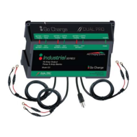
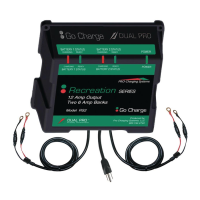
The Industrial Series chargers come in three models, each with different output configurations:
All units operate with a VAC input range of 90VAC-264VAC. The charge cable assemblies are equipped with a temperature sensor at the junction of each set of ring terminals.
Installation: The chargers are designed for permanent installation in a well-ventilated area. Before installation, ensure no electrical connections are made to the power supply (AC) or battery (DC). When mounting in a boat, choose a flat surface as high above the water level as possible, or a compartment wall strong enough to support the charger's weight. Use the provided stainless steel screws and silicon sealer for secure and waterproof installation. The mounting brackets may have keyholes for easier installation.
Battery Preparation: Before connecting, ensure battery caps are securely in place. Clean the battery case and posts with a baking soda and water solution, being careful not to get any solution inside the case. Periodically clean posts, terminals, and connectors to ensure maximum conductivity. For wet cell batteries, add distilled water to each cell until the acid reaches the level specified by the manufacturer, helping to purge excessive gas. Follow manufacturer's recharging instructions regarding cell caps.
Connection: Route charge cables from the charger to the batteries, avoiding sharp objects, and secure them with supplied wire ties. Connect the red (positive/+) lead ring terminal to the positive (+) battery post and the black (negative/-) lead ring terminal to the negative (-) battery post for each 12V battery.
Power Connection: Always make the extension cord connection on the charger side first. Use an industrial-grade/heavy-duty UL approved and grounded extension cord. Plug the extension cord into a 120VAC GFCI protected A/C outlet. The unit will operate with a VAC input range of 90VAC-264VAC. Always remove the extension cord from the A/C outlet first when charging is completed, then unplug the charger.
Charging Process: Once plugged in, the system will simultaneously and independently charge batteries to 100%. Each charging bank will enter a "float" stage once the battery is charged, monitoring and maintaining it indefinitely. It is recommended to leave the system plugged in to reduce sulfation and keep batteries fully maintained.
LED Indicators: Each charging bank provides charging information using two Light Emitting Diodes (LEDs):
Safety Precautions:
General Maintenance: The system is designed for minimal maintenance once installed. The float maintenance mode helps reduce sulfation on lead plates, keeping batteries ready for optimal performance.
Troubleshooting:
For any product, installation, or service questions, contact technical support at 800.742.2740. The manufacturer offers a limited warranty of 18 months from the date of retail purchase against defective materials and/or workmanship. The warranty is void if the product is misused, improperly maintained, handled carelessly, incorrectly operated, disassembled, altered without authorization, or if the serial number is removed or repair is attempted by unauthorized personnel.
| Brand | PRO Charging System |
|---|---|
| Model | Industrial Series |
| Category | Battery Charger |
| Language | English |