EasyManua.ls Logo

Procom DGC-6D - User Manual

Procom DGC-6D
10 pages
Print Icon
To Next Page IconTo Next Page
Loading...
Question and Answer IconNeed help?

Do you have a question about the Procom DGC-6D and is the answer not in the manual?

Summary

DGC-6 D Automatic Engine Controller Overview

Introduction to DGC-6 D

Microprocessor/microcontroller based automatic generator start and supervisory device.

Protection and Supervision Features

Details voltage protection, speed supervision, cranking attempt, and other safety features.

Measurement and Display Capabilities

Explains parameters displayed on LCD and LEDs for voltage, current, frequency, and RPM.

LED Indicators

Lists LED indicators for Mains, Generator, Battery, Frequency, and Load status.

Integrated Timers

Lists various timers for start delay, crank, supervision, and restoration.

Device Functionality and Operation

Auto and Manual Mode Operation

Explains mode selection, auto mode operation, genset starting, and fault monitoring.

Engine Solenoid Configuration

Details two modes for engine solenoid contact: cranking and running, and stopping the generator.

Display and Annunciations

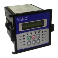
Describes the LCD display for voltages and the 14 LEDs for annunciations.

Programming Mode and Setting Table

Details programmable parameters, default settings, and operational ranges.

Switch Panel and Fault Management

Switch Panel Description

Explains the function of each switch: Next, Increment, Decrement, Reset, MCB, and GCB.

Fault Management

Categorizes faults into Internal and External, describing their detection and impact.

Internal Faults Details

Details internal faults like Generator Fail to Start, Voltage Unhealthy, Over-Speed, Battery issues.

External Faults Details

Details external faults like Low Lube Oil Pressure (LLOP) and High Water Temperature (HWT).

Fault Reset Procedures

Explains how to reset internal faults and LLOP, and conditions for HWT/Low fuel reset.

Technical Specifications and Diagrams

Technical Specifications

Provides technical specifications for AC voltage, accuracy, battery voltage, and contact ratings.

Connection Diagram DGC-6 D

Illustrates wiring connections for the DGC-6D model.

Connection Diagram DGC-6 D11

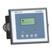
Illustrates wiring connections for the DGC-6D11 model.

Overview

The DGC-6D/6D1I is a microprocessor/microcontroller-based automatic generator start and supervisory device, designed for ease of operation. Housed in a 96 x 96 flush-mounted enclosure, it serves as an ideal replacement for logic-based AMF (Automatic Mains Failure) units by integrating the functions of discrete logic-based AMF units into a single compact device, thereby simplifying panel wiring and reducing overall size.

Function Description:

The DGC-6D/6D1I monitors the Mains supply. If the Mains supply voltage varies beyond the set limits (under and over voltage) for more than the Mains supervision time, the DGC-6D initiates the genset start sequence. It provides a cranking signal via a potential-free contact to the crank motor. The crank command is withdrawn upon detection of engine start, either by an external engine start input or by the build-up of generator voltage. The maximum duration of the crank command and the number of crank attempts are user-settable. If the generator fails to start after the programmed number of attempts, the FST (Fail to Start) LED blinks, indicating a fault, and the hooter is activated.

While the genset is running, the DGC-6D monitors for external faults such as LLOP (Low Lube Oil Pressure), HWT (High Water Temperature), and Emergency Stop, as well as the voltage healthiness. Upon detection of any fault, the genset is stopped after a set time delay, and the hooter is activated. When a healthy EB (Electricity Board) supply is restored for the set duration, the genset is stopped after a user-set recooling time. Load changeover is performed automatically.

The device supports both Auto and Manual/Test modes. In Auto mode, the unit automatically manages genset operation based on Mains supply conditions. In Manual/Test mode, the DG can be started or stopped by pressing the Start and Stop buttons, respectively. The main contactor (MCB) and generator contactor (GCB) can also be switched on/off manually.

The engine solenoid contact (Terminals 15 & 16) can be configured in two modes:

  • Mode 0: The fuel solenoid contact changes from Normally Open (NO) to closed during cranking and remains closed while the genset is running. It opens to stop the generator.
  • Mode 1: The fuel solenoid contact remains open during cranking and while the genset is running. It closes for a user-programmed time to stop the generator.

Important Technical Specifications:

  • AC Voltage Withstand: 330 VAC continuously (Phase to neutral)
  • Measurement Accuracy: 1%
  • Surge 1.2/50Usec: 2.5KV
  • Battery Voltage: Suitable for 12V/24 VDC System
  • Max. Battery Voltage: 35V
  • DC Interruption Time: 1 Sec.
  • Output Contact: 5 NO (Normally Open)
  • Contact Rating: 230V / 6A
  • Cut out Dimensions: 90mm X 90mm
  • Depth: 120mm
  • Digital Input Level: Battery Voltage (Negative)

Protection & Supervision:

  • 3-phase Under & Over voltage protection for EB supply (True RMS measurement).
  • Phase under & over voltage protection of Generator supply (True RMS measurement).
  • User-programmable Cranking attempt.
  • Generator over speed supervision.
  • DC Battery Voltage supervision (Under & Over voltage).
  • External fault detection (2 digital inputs).
  • External engine running signal.
  • DG Fail to Start supervision and indication.
  • DG Fail to Stop supervision and indication.
  • The unit remains fully operational even if battery voltage falls to zero volts for one second.

Measurement & Display:

The DGC-6D, equipped with a four-seven segment display, shows:

  • EB voltages of RYB phase.
  • Generator voltage.
  • Generator Current (Only in model DGC-6D11).
  • DC battery voltage.
  • Generator frequency.
  • RPM.
  • Cumulative Run Hour (five digits).
  • Set values.

Usage Features:

  • LED Indications:
    • Status Indication of Mains Supply (R,Y,B).
    • Status Indication of Generator Voltage (G).
    • Status indication of Battery Voltage (Vb).
    • Generator frequency (Hz).
    • Load on generator (GCB).
    • Load on EB (MCB).
    • Auto / Manual (Auto).
    • Emergency fault (Emer).
    • DG Fail to Start (FST).
    • DG Fail to Stop (FSP).
    • High Water Temperature (HWT).
    • Low Lube Oil Pressure (LLOP).
  • Timers: The device incorporates various programmable timers, including DG Start delay, Generator Voltage Supervision, Max. cranking time, Crank gap time, No. of crank attempts, Mains restoration time, DG recooling time, High Water temperature, Low Lube Oil Pressure, Generator over speed delay, and Timer for stop solenoid.
  • Programming Mode: Accessible by simultaneously pressing Reset & A/M keys. This mode allows users to configure various parameters such as Mains Over/Under Voltage, Mains voltage supervision time, Generator Start Delay, Generator Over/Under Voltage, Generator Supervision Time, Generator O/S (Over Speed), No. of Crank Attempt, Crank Time, Crank Delay, Gen. pickup Voltage, Generator warm up time, Mains Restoration Time, Generator Recooling Time, Stop solenoid time, Low Fuel time delay, LLOP Time delay, HWT Time delay, GCB to MCB time delay, Hooter Reset Time, Over Current (DGC-6 only), and O/C Delay (DGC-6 only). For the DGC-6D1I, CT Ratio is also programmable.
  • Switch Description:
    • ↑ OR A/M (Next): In normal operation, selects voltages on display (Mains R, Y, B, Generator, Battery). In programming mode, selects the next parameter. Long press (4+ sec) toggles Auto/Manual mode.
    • + OR Start (Increment/Start): In programming mode, increments parameter value. In manual mode, used for ignition/crank command.
    • - OR Stop (Decrement/Stop): In programming mode, decrements parameter value. In manual mode, used to stop the DG.
    • Reset: Resets hooter and fault signals. First press resets hooter, next resets faults. Long press (1+ sec) resets both.
    • MCB: Switches Mains contactor on/off.
    • GCB: Switches Generator contactor on/off.

Maintenance Features:

  • Faults: The device categorizes faults into Internal and External.
    • Internal Faults: Detected by the system itself, including Generator Fails to Start, Generator Voltage Unhealthy, Generator Fails to Stop, Over-Speed, and Battery Under or Over voltage. Corresponding LEDs blink, and the hooter is activated.
    • External Faults: These faults are not reflected by the generator voltage and require external signals. Examples include Low Lube Oil Pressure (LLOP), High Water Temperature (HWT), and Emergency Stop.
      • LLOP: Active only when the generator is running. Inactive if the generator is off due to Mains availability or another fault.
      • HWT & Low fuel: Always active regardless of generator condition (ON or OFF). These faults have a variable timer and are generated after the programmed delay.
  • Fault Reset:
    • Internal Faults: All internal faults can be reset by pressing the Reset Key.
    • LLOP: Can be reset by pressing the Reset Key.
    • HWT/Low fuel: Cannot be reset until the conditions causing the fault are cleared. The generator will not start until these faults are cleared.
  • Fault Response: Immediately after a fault activation, the generator stops, the Generator Circuit Breaker contact is released, and after a 125ms delay, the load is transferred to Mains Supply. The hooter remains active for 30 seconds if not reset.
  • Contacts: All contacts are normally open (NO) type, except the Mains Circuit breaker contact, which is Normally Closed (NC) type.

The DGC-6D/6D1I is a robust and comprehensive solution for automated generator management, offering detailed monitoring, protection, and user-friendly control.

Procom DGC-6D Specifications

General IconGeneral
BrandProcom
ModelDGC-6D
CategoryController
LanguageEnglish

Related product manuals