Duty Cycle
Duty Cycle is the equipment
specifications which defines the number of
minutes within a 10 minute period that a
piece of equipment can safely operate.
Example for welding duty cycle
30%@170Amps is as follows
, which
means that it continuously operates for 3
minutes at maximum output during a 10
minute period.
CAUTION: Failure to observe the duty
cycle limitations of this
MIG MACHINE
can easily damage this equipment, and
will void warranty.
UNPACKING
When unpacking, checks to make sure the
following parts are included.
Inverter welding machine with
MIG torch with Power Cord
Ground cable with Clamp
If any parts are missing or broken, please
call
PROCRAFT at the number on the
cover of this manual.
Preparing Your Work Area
1. You must have a sturdy work table
that is open below the area you are
welding. Molten slag will be blown
through the work metal, and must be
able to fall away freely
2. Your work table must allow the work
metal to be firmly clamped to prevent it
accidentally falling or moving.
3. The floor and surrounding area of your
work site must not be flammable. A
clean cement floor is recommended.
The cutting process will eject molten
metal slag onto the floor, and it will
scatter for 8-10 feet or more in any
direction. Have an adequate fire
extinguisher available if needed.
ASSEMBLY
Attach air supply:
Caution: Do not use an Argon/Mixed
pressure regulator/flow meter with CO
2
Shielding gas. To use CO
2
Shielding gas,
you must install a CO
2
Shielding gas
pressure regulator/flow meter.
1. Make sure the Flow Adjust on the
Pressure Regulator/Flow Meter is
turned off. Then Pressure
Regulator/Flow Meter (not included)
firmly onto the cylinder valve.
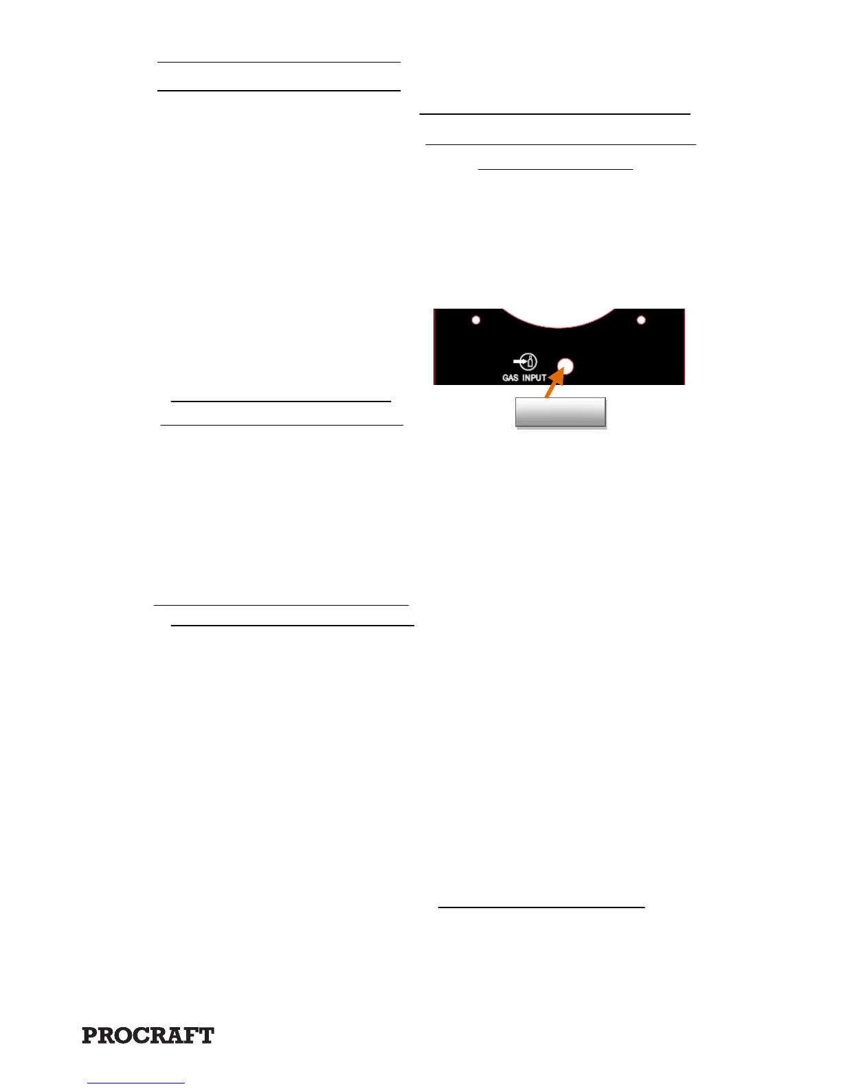
2. Connect the gas air inlet (1) to your
supply CO
2
Gas supply by one air
hose (not supplied). And remember to
fasten it with coupling.
3. Adjust the flow rate of the gas by
turning the Flow Adjust. The typical
flow rate is 10-30 CFH (cubic feet per
hour). Make sure to check the
Welding Wire manufacturer’s
recommended flow rate.
Front Panel and Instruction
Gasinlet(1)