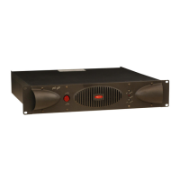
PRL500 - 900 - 1300 T e s t & C a l i b r a t i o n
Required Test Equipment:
• Function Generator
• 20 Mhz Dual-channel Oscilloscope
• Power Load Bank (4Ω - 350W min.)
• 2 Digital Multimeters (Tester)
• PROEL Test Cable
• Variac (0V ac – 230V ac, 15A)
Test Procedure
Connections:
• Connect the Function Generator output on CH1 input Jack or XLR socket.
• Connect the Power Load Bank with Speakon on the output sockets.
• Connect the Dual-channel Oscilloscope on Binding Post outputs.
• Connect the PROEL Test Cable to the TP Test Points of the amplifier and the two
other side terminals to the Testers setted at 200mV range.
• Set the Variac at 0V and connect its output to the mains cable of the amplifier.
Verifying:
• Switch on the amplifier, then slowly rise the Variac voltage till 230V and check the
value on the Testers is the most low as possible (few mV). If not check the correct
mounting of MJ21193/MJ21194 transistors.
• In same time the relays are activated and the protect red led turns off.
• Set the amplifier in parallel mode.
• Set the Function Generator on 1KHz sinewave at 0.2V RMS and check on the
Oscilloscope monitor the output signals have the same amplitude and phase.
• Then rise the Function Generator amplitude till 1V RMS and check on the
Oscilloscope monitor the output signal is not squared.
• Set the amplifier in bridge mode.
• Set the Function Generator on 1KHz sinewave at 0.2V RMS and check on the
Oscilloscope monitor the output signals have the same amplitude and opposite
phase.
• Then rise the Function Generator amplitude till 1V RMS and check on the
Oscilloscope monitor the output signal is not squared.

 Loading...