Do you have a question about the PROEL PSW2600 and is the answer not in the manual?
Essential precautions to prevent electric shock, fire, and damage from moisture or heat.
Guidelines for safe placement away from water, heat, and ensuring proper ventilation.
Overview of the PSW series, its models, and key technological features like OSC™.
Information on product packaging, integrity tests, and handling claims for transport damage.
Details on the 24-month warranty, defect reporting, and Proel's responsibilities.
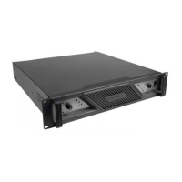
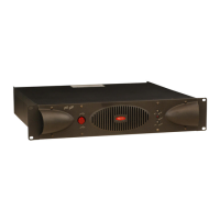
Instructions for mounting the amplifier in a 19-inch rack with proper ventilation.
Specifies intended use for audio signals and connection types for passive loudspeakers.
Explanation of safety symbols, particularly those indicating dangerous electrical terminals.
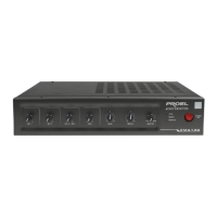
Description of the power ON/OFF switch and its associated blue indicator LED.
Details on the volume attenuating knobs for channels A and B, and their use in BRIDGE mode.
Explanation of CLIP, BRIDGE mode, and BI-COLOUR SIGNAL LEDs for monitoring amplifier status.
Information on the red DC PROT and TEMP LEDs, indicating protection activation and overheating.
Details about the forced-air cooling system and the importance of unobstructed air vents.
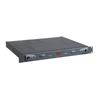
Description of balanced XLR inputs and push-button selectors for STEREO, PARALLEL, BRIDGE, and GAIN modes.
Explanation of OSC™ ON/OFF, GROUND LIFT, and power output connectors (SPK4MP, binding posts).
Details on forced-air ventilation and proper power cord connection requirements.
How channels A and B operate independently with separate input signals.
Using CHA input to drive both channels, adjusted by individual volume controls.
Mono operation using CHA input and 'Bridge' binding posts for higher power output.
Guidance on spacing and fan kits for multiple amplifiers in a rack for optimal ventilation.
Description of the unit's forced cooling system, air intake, and exhaust.
Explanation of the OSC™ circuit that prevents signal distortion by controlling saturation.
Schematic representation of the amplifier's internal signal flow and component interactions.
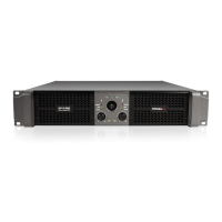
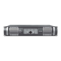
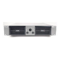
Top view showing overall dimensions and front view with control layout.
Rear view with connections and side view detailing physical attributes.
Recommended speaker pairings for PSW1800 and PSW2600 models.
Details on XLR connectors, power connectors, and recommended audio cables.
Guides for identifying problems based on CLIP, TEMP, and DC PROT indicator lights.
When to contact qualified personnel for maintenance or repair due to specific damages.