10
MONTAGGIO RACK - CIRCOLAZIONE DELL’ARIA
RACK MOUNTING – AIR FLOW
MONTAJE EN BASTIDOR – FLUJO DE AIRE
PSW SERIES
MONTAGGIO RACK Italiano
Se più amplificatori vengono montati in un rack
con scarsa ventilazione, il calore prodotto
riscalderà molto il loro interno, causando una
riduzione delle prestazioni. In particolare, in
caso di montaggio in rack, la cui parte poste-
riore non può essere lasciata aperta, seguite
seguenti istruzioni:
• RACK
Lasciate uno spazio di circa 10 cm o più tra
il pannello posteriore del rack e quello del-
l’amplificatore.
• VENTOLA
Utilizzate una ventola con una aerazione
minima di 1,5m
3
/min o superiore ed una
pressione statica massima di 5mmH
2
O o
superiore.
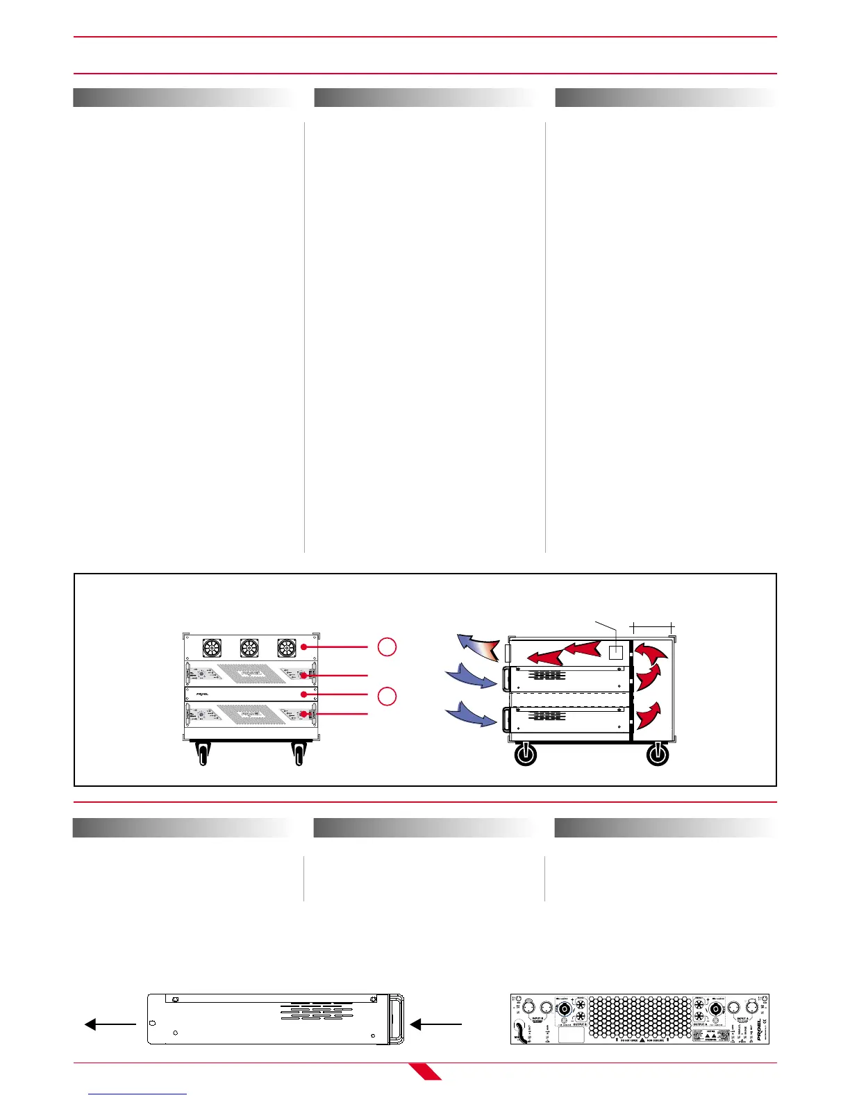
• MONTAGGIO
Installate il kit della ventola nello slot supe-
riore (1) o sul pannello superiore del rack e
installate un pannello fittizio (2) tra due
amplificatori.
Se l’unità è montata in un rack ed è trasporta-
ta frequentemente, si raccomanda di supporta-
re il retro dell’unità con un paio di staffe
metalliche, per ciascun lato.
ESEMPIO DI MONTAGGIO DELL’AMPLIFICATO-
RE (FIG.2)
MONTAJE EN BASTIDOR Español
Si se montan más amplificadores de potencia en
un bastidor con escasa ventilación, el calor pro-
ducido por los amplificadores de potencia causará
el calentamiento excesivo del interior de los
amplificadores, causando una disminución nota-
ble de su rendimiento. Particularmente, cuando
efectúen el montaje en un bastidor cuya parte
trasera no se puede dejar abierta, háganlo respe-
tando las siguientes instrucciones:
• Bastidor
Dejar un espacio de aproximadamente 10 cm o
más entre el panel trasero del bastidor y el
panel trasero del amplificador de potencia.
• Ventilador
Utilizar un ventilador con una aeración minima
de 1,5m
3
/min o superior y una presión estáti-
ca máxima de 5mmH
2
O o superior.
• Montaje
Instalar el juego de ventiladores en la ranura
superior (1) o en el panel superior del bastidor
e instalar un panel separador (2) entre los dos
amplificadores de potencia.
Si la unidad es apilable y se transporta con fre-
cuencia, recomendamos que la parte trasera de la
unidad se soporte con un par de abrazaderas
metálicas, una en cada lado.
EJEMPLO DE MONTAJE DEL AMPLIFICADOR DE
POTENCIA (ILUSTRACIÓN 2)
RACK MOUNTING English
If multiple high-power amp units are mounted
in a poorly ventilated rack, the heat from the
amplifiers will cause the interior of the amp to
become very hot, causing the performance of
the amps to be impaired. If mounting in a rack
whose rear part cannot be left open, please
mount according to the following instructions:
• RACK
Leave a gap of approx. 10 cm or more
between the rear panel of the rack and the
rear panel of the amplifier.
• FAN
Use a fan featuring a minimum ventilation
of 1,5m
3
/min or more and a maximum static
pressure of 5mmH
2
O or more.
• MOUNTING
Install the fan kit on the top slot (1) or the
top panel of the rack and install a blanking
panel (2) between two amplifiers.
If the unit is rack mounted and transported
frequently, it is recommended to support the
rear part of the unit with a pair of metal
brackets, one on each side.
EXAMPLE OF AMPLIFIER MOUNTING (FIG. 2)
CIRCOLAZIONE DELL’ARIA Italiano
Questa unità presenta un sistema di raffredda-
mento forzato nel quale l’aria entra attraverso le
aperture frontali ed esce dalla parte posteriore.
FLUJO DE AIRE Español
Esta unidad está caracterizada por un sistema
de refrigeración forzada en el que el aire entra
a través de las aberturas delanteras y sale de la
parte trasera.
AIR FLOW English
This unit uses a forced cooling system in which
air comes in through the front opening and
goes out the rear.