EasyManua.ls Logo

ProForm 67005C User Manual

ProForm 67005C
2 pages
To Next Page IconTo Next Page
Page #1 background imageLoading...
Page #1 background image
Calibration to Match Your Engine
• 8 CYL. – No adjustment is necessary
• 6 CYL. – Clip BROWN wire loop only
• 4 CYL. – Clip BROWN and ORANGE wire loops
Insulate cut wire with electrical tape!
www.proformparts.com/tech
High Performance Adjustable RPM Shift Lights
RED
12V IGNITION SWITCH (+)
GROMET
IN FIREWALL
BLACK
BLACK
GREEN
GREEN
GREEN
On standard
ignition, GREEN
wire attaches to
coil negative (-).
On electronic ignition,
such as GM, HEI or
MSD, connect wire
to the tach terminal.
GOOD
ENGINE
GROUND
ELECTRONIC
IGNITION
STANDARD
IGNITION
OR
TACH
TERMINAL
12V BATTERY
2.75"
HIGH
1.5"
HIGH
5"
LONG
© 2003 Specialty Auto Parts U.S.A., Inc. All rights reserved.
Part # 67005C Shift Light
Part # 67005SC Shift Light
Part # 67005BC Shift Light
Part # 67005RC Shift Light
Shift Light Dimensions
Troubleshooting
Proper shift light operation requires a good ground and securely connected wiring. If you are having trouble, double-check your
ground and be certain that you have 12 volt power. Be sure you have followed the wiring diagram instructions above. We
recommend you avoid crimp connectors and solder all connections if possible. Soldering your connections will minimize any
loose connections that may cause problems.
— WARNING —
ATTACH ONLY TO TACH TERMINAL. Warranty will be void if connected to coil on MSD ignitions. You must check with the
engine manufacturer for recommended safe shift points PRIOR to setting your shift point on this shift light.
Failure to comply with this may lead to over-revving of your engine and may cause serious damage to your engine.
LIMITED WARRANTY: Specialty Auto Parts U.S.A., Inc. will, within a reasonable period of time, repair or replace free of charge any part listed in this catalog which upon careful inspection is found, in our sole judgement,
to have material or manufacturing defects, provided it is received within thirty (30) days of date of purchase accompanied by a sales slip, the original packaging, and an authorized Return Merchandise Authorization
number (RMA). End-users should return the part to the seller from whom they made their purchase. The seller will obtain an RMA by calling (586) 774-2500. To make a warranty claim, the seller must return the part to
Specialty Auto Parts U.S.A., Inc., 26708 Groesbeck Highway, Warren, MI 48089, freight prepaid. There is absolutely no warranty for the following conditions: (1) Any parts used on racing applications, (2) Any part
that has been physically or mechanically altered, (3) Any part that has been improperly installed or maintained, (4) Any part used in improper applications or not used in conjunction with the proper parts. There are no
implied warranties of merchantability or fitness for a particular purpose. There are no warranties, which shall extend beyond the warranty description herein. Specialty Auto Parts U.S.A., Inc. will not be responsible
for incidental damages, consequential damages, property damages, or personal injury damages to the extent permitted by law. PLEASE NOTE: SOME STATES DO NOT ALLOW LIMITATIONS ON HOW LONG IMPLIED
WARRANTIES MAY LAST OR DO NOT ALLOW EXCLUSIONS OR LIMITATIONS OF INCIDENTAL OR CONSEQUENTIAL DAMAGES, SO THOSE EXCLUSIONS OR LIMITATIONS MAY NOT BE APPLICABLE TO
YOU. Some of the parts listed in this catalog are not legal for sale or use in California or any pollution controlled vehicles. Installation of proform and proform factory performance parts may adversely affect the warranty
coverage on your vehicle. Specialty Auto Parts U.S.A., Inc. assumes no liability for errors made in component selections or installations. Specialty Auto Parts U.S.A., Inc. reserves the right to make necessary changes
in products it manufactures and markets at any time to improve product performance. Proform and Factory Performance Parts are registered trademarks of Specialty Auto Parts U.S.A., Inc.
BEFORE YOU START!
Always Wear Safety Glasses!
Use Extra Caution when Working
with Electrical Components
Mounting
The versatile shift light base design permits many mounting possibilities, using ordinary
machine screws. In some cases mounting with a hose clamp may be preferred.
This shift light is equipped with a rubber lined shock mounting ring: therefore, proper
installation demands that nothing should touch the housing or the mounting ring.
Mounting the shift light on the dashboard, where windshield clearance could be a problem,
is permitted by the extra length on the mounting bracket.
Question and Answer IconNeed help?

Do you have a question about the ProForm 67005C and is the answer not in the manual?

ProForm 67005C Specifications

General IconGeneral
BrandProForm
Model67005C
CategoryAutomobile Accessories
LanguageEnglish

Summary

Before You Start

Safety Precautions

Essential safety measures for electrical work, including wearing safety glasses.

Wiring Diagram and Connections

Visual guide for connecting the shift light to the 12V battery, ignition, and tach terminal.

Calibration Procedure

Steps to adjust the shift light for 4, 6, or 8-cylinder engines by clipping wire loops.

Shift Light Dimensions

Physical size specifications of the shift light unit for installation planning.

Mounting Guidelines

Mounting Methods

Details on using machine screws, hose clamps, and shock mounting for installation.

Troubleshooting and Best Practices

Connection Troubleshooting

Ensuring good ground, 12V power, and recommending soldering over crimp connectors.

Important Warnings and Warranty

Limited Warranty Terms

Information on product warranty, repair, replacement, and exclusions.

Critical Operational Warning

Warning about connecting only to tach terminal and checking safe shift points to avoid engine damage.

Late-Model Installation Tips

GM Cars & Trucks

Installation tips for Buick Regal T-Types and Grand Nationals.

HEI Distributors

Connecting the shift light to the C-terminal/wire or TAC terminal.

GM Dual Connector

Wiring the shift light through the GM dual connector.

LT1 Engines

Connecting the shift light to the brown wire on the 80-pin connector.

LS1 Engines 1999+

Wiring the shift light to the firewall connector on LS1 engines.

Ford Cars & Trucks TFI Distributors

Connecting the green wire with yellow stripe to the coil.

3.8L and 4.6L Mustangs (1996-1998)

Connecting the green wire to pin 48 on the Powertrain Control Module.

4.2L, 4.6L, and 5.4L F-Series Trucks (1996-1998)

Connecting the green wire to pin number 44 on the Powertrain Control Module.

Range Trucks

Connecting the green wire to pin number 4 on the Powertrain Control Module.

Chrysler Cars & Trucks

Connecting the green wire to the gray wire with blue stripe.

Sport/Import Applications

Connecting the green wire to the tach terminal on various ignition systems.
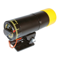