10
Electrical Connection Instructions
ELECTRICAL CONNECTION INFORMATION
DC
WIRING
PD1610(1kW)
WIRE LENGTH MIN. WIRE SIZE
STRIP LENGTH CONNECTION INFO
0-5 ft. #2 AWG
Strip 3/4” (19 mm) insulation from
each cable prior to installation. Do
not leave excess copper exposed.
Tighten lugs to a torque of
100 in-lbs (11.3 N-m).
Do not over tighten.
Fuse: min. 100A for full load
(See NEC for safety codes)
5-10 ft. #1 AWG
10-15 ft. #1/0 AWG
PD1618(1.8kW) 0-10 ft. #2/0 AWG
Strip 3/4” (19 mm) insulation from
each cable prior to installation. Do
not leave excess copper exposed.
Tighten lugs to a torque of
200 in-lbs (22.6 N-m).
Do not over tighten.
Fuse: min. 200A for full load
(See NEC for safety codes)
PD1620(2kW) 0-10 ft. #2/0 AWG
PD1610(1kW) 0-100 ft. #14 AWG Solid
Strip 0.6” (15 mm) insulation from
each wire prior to installation. Do not
leave excess copper exposed.
Standard 3/8” trade strain
relief . No torque wrench re-
quired
AC
WIRING
PD1618(1.8kW) 0-100 ft. #14 AWG Solid
PD1620(2kW) 0-100 ft. #12 AWG Solid
GND
WIRING
PD1600 Series Any #8 AWG
Strip 0.5” (13 mm) insulation from
each wire prior to installation. Do not
leave excess copper exposed.
Torque ground lug to 30-50
in-lbs.
NOTE: To ensure optimum performance all input wires should be as short as possible. Failure to meet minimum recommended wire size will result in reduced perform-
WARNING: FIRE, SHOCK, AND ENERGY HAZARD
Make sure wiring is disconnected from all electrical sources before
handling. All wiring must be done in accordance with local and na-
tional electrical wiring codes.
Failure to follow these instructions may result in serious injury or
death.
Electrical Connection Instructions
1. Ensure all power sources are disconnected from the inverter
2. Remove the wiring cover
3. Remove AC Input knockouts and AC Output knockouts
4. Install 3/8” strain relief in AC Input and AC Output ports
5. Connect AC Out terminal block (Ground, Neutral, and Line)
6. Connect AC In terminal block (Ground, Neutral, and Line)
7. Tighten strain relief (if applicable)
8. Connect DC terminals (positive and negative) to battery with properly sized wires, 5/32” hex (PD1610); 1/4” hex (PD1618/20)
9. When connecting DC wires a small spark may occur. This is normal charging of the inverter’s internal capacitors
10. Provide external strain relief for DC wires
11. Connect equipment ground stud to a grounding point (typically the vehicle’s chassis) using a 5/32” hex key
12. Re-install the wiring cover
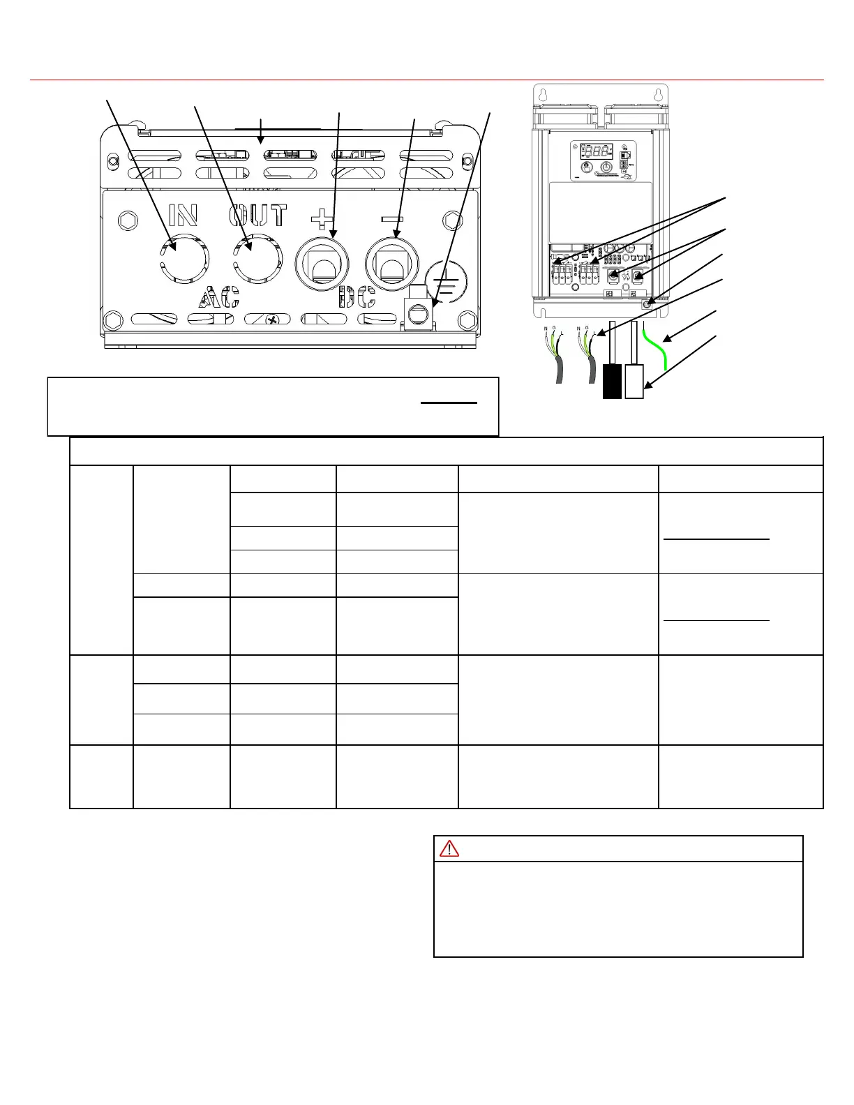
Figure 9 Electrical Connections Top View
Figure 8 Electrical Connections Side View
PD1600 series inverters are compatible with BOTH
lithium and lead acid batteries.
DC Wiring
Ground Wiring
AC Input Wiring
Cover
AC Output Negative DC
Connection
Positive DC
Connection
Equipment
Ground
AC Wiring
DC Lugs
Ground Lug
AC Terminal
Blocks