EasyManua.ls Logo

Progressive Dynamics PD2020 - User Manual

Progressive Dynamics PD2020
8 pages
To Next Page IconTo Next Page
Loading...
-1-
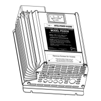
ELECTRONIC MARINE CONVERTER/CHARGER
Owners Manual
Models PD2020, PD2030, PD2040, PD2050, PD2060, PD2080
Thank you for purchasing the INTELI-POWER MARINE converter/charger. The
INTELI-POWER MARINE converter from Progressive Dynamics Inc. has been
designed and manufactured to meet the harsh environmental, mechanical and electrical
conditions that exist in the marine industry. The INTELI-POWER MARINE converter
incorporates our Patented Tri-Power circuitry and modern Microcontroller technology to
provide a Total Charge Management System for recharging and maintaining marine
batteries by providing 3 modes of operation, Normal, Boost, Trickle.
Progressive Dynamics Inc
507 Industrial Rd.
Marshall, MI 49068
(269) 781-4241
Fax (269) 781-7802
www.progressivedyn.com
-2-
Table Of Contents
IMPORTANT SAFETY INSTRUCTIONS ............................... -3-
PERSONAL PRECAUTIONS .......................................... -3-
LOCATING THE INTELI-POWER MARINE CONVERTER/CHARGER ..... -4-
DC CONNECTION PRECAUTIONS ................................... -5-
INSTALLING THE INTELI-POWER MARINE CONVERTER ............. -5-
OPERATING THE INTELI-POWER MARINE CONVERTER/CHARGER .... -10-
MAINTAINING THE INTELI-POWER MARINE CONVERTER/CHARGER
.......................................................... -11-
TROUBLE SHOOTING GUIDE ...................................... -11-
SAMPLE WIRING DIAGRAMS FOR SERIES/PARALLEL CONNECTIONS
.......................................................... -12-
SPECIFICATIONS ................................................. -14-
MARINE BATTERY CHARGER LIMITED WARRANTY ................ -16-

Questions and Answers

Progressive Dynamics PD2020 Specifications

General IconGeneral
BrandProgressive Dynamics
ModelPD2020
CategoryBattery Charger
LanguageEnglish

Summary

Important Safety Instructions

General Safety Guidelines

Covers battery type, environmental exposure, attachment use, and service procedures.

Battery Handling and Precautions

Includes personal safety, first aid, fire prevention, tool handling, and frozen battery warnings.

Ventilation and Cleaning

Ensures proper ventilation and safe cleaning of battery terminals and work area.

Converter Location Guidelines

Optimal Placement and Clearance

Locate in well-ventilated area, away from battery gases and acid drips, with clearance.

Converter Location and Mounting

Location Guidelines

Optimal placement away from battery gases and acid, with adequate ventilation.

Mounting Procedures

Details on mounting location, hardware selection, and mounting the converter.

DC Connection Safety and Grounding

Connection Precautions

Connect/disconnect DC output after AC disconnect; ensure proper grounding.

Converter Installation Steps

Mounting and Drip Shield

Procedures for mounting the converter and installing the drip shield.

Wiring and Connections

Covers wire gauge, AC/DC connections, and external fuse installation.

Final Checks and Power Up

Steps for final wiring check and applying power to the unit.

Operating the Converter;Charger

Safety Precautions During Operation

Always follow safety instructions in Part 1 before operating the converter/charger.

Converter Operation Modes

Converter automatically selects Normal, Boost, Trickle, or Equalization modes for optimal battery charging.

Internal Fuse Replacement Procedure

Replace internal fuses (30 Amp ATC) only if battery is connected in reverse.

Converter Maintenance

Maintenance Requirements

No user adjustments needed; only periodic checking of connections by a qualified person.

Troubleshooting Guide

Troubleshooting: No Output

Steps for no output: check supply, fuses, distribution panel, and circuit faults.

Troubleshooting: Internal Fuse Issues

Steps for blown fuses: check for short circuits, reverse polarity, or component faults.

Troubleshooting: Cycling Issues

Steps for cycling: check for overheating, over-voltage, or compartment temperature.

Troubleshooting: Low Output

Steps for low output: check load, input voltage, or battery cell condition.

Wiring Diagrams

Parallel Wiring Configuration

Wiring chargers in parallel for increased current to the 12V house battery system.

Wiring Diagrams

Series Wiring Configuration

Wiring chargers in series for combined 12V and 24V charging systems.

Troubleshooting Checks Before Replacement

Check Converter Output Voltage

Verify converter output voltage is above 13 volts using a DC voltmeter.

Check AC Power Source Voltage

Check AC power source voltage is between 104 and 130 volts.

Check Internal Fuses

Check internal fuses for blowing due to reverse battery or DC output lead connection.

Specifications

Model Specifications

Technical specifications for various INTELI-POWER MARINE converter models.

Marine Battery Charger Limited Warranty

Warranty Terms and Conditions

Details the limited warranty, duration, exclusions, and claim procedures for the chargers.