26 27
- Power
DC CURRENT VOLTAGE (nominal) 12Vdc
TOLERANCE: – 10% / + 20% (* note)
DC CURRENT VOLTAGE (MIN÷MAX): 10,8 ÷ 14,4 Vdc
(*note) The value indicated takes into account average motor features and estimated work load. The value indicated here is the mini-
mum value guaranteed for the system to work at maximum declared load.
With reference to picture 1, voltage must be applied to clamps 7 and 3 of the 8-pole faston connector, making sure to connect the
positive pole with the clamp and the ground to clamp 3.
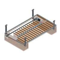
5.2.2 MOTOR CONNECTIONS
PICTURE 2 – MOTOR CONNECTOR, WIRE INLET, SIDE VIEW
The motor has a 5-pole connector for a female movable connector represented in picture 2. The picture shows the connector from the
cables connection side.
Wires No. 5 and 4 are motor connections, for the wiring please refer to diagram in picture 3.
Wires No. 2 and 1 are for the timer connection. This signal is a closing contact directly powered by the board. The voltage value detec-
ted when operating is from 0 to 5Vdc.
Wire No. 3 is not used.
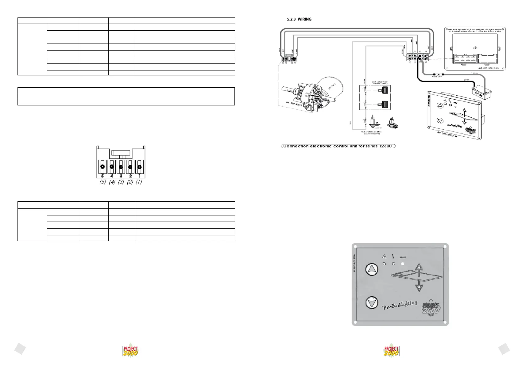
5.2.3 WIRING
PICTURE 3 – WIRING DIAGRAM
The diagram in picture. 3 summarizes all of the connections between the board and the other items that should be established in order
for the system to work correctly.
The motor connections (pin 8 and 4 of the 8-pole connector) and power connections (pins 3 and 7 of the 8-pole connector) must be
carried out exactly as shown in the picture, whereas the timer connection (pins 2 and 6 of the 8-pole connector) and the limit switch
connection (pins 1 and 5 of the 8-pole connector) have no polarity and can be swapped.
Follow the instructions provided with the bed lifting system (wiring diagram).
Comply with current CEI regulations during the installation operation.
The Manufacturer provides a set of standard cables for installation with the bed lifting system. After electric installation it will be pos-
sible to start up and test the system.
The Manufacturer shall be held harmless for any bed lifting system malfunctioning caused by not perfectly functioning electric system
connections and to an wrong installation on the vehicle.
5.2.4 STARTING AND OPERATING
PICTURE 4 – CONTROLLER FRONT PANEL WITH ELECTRONIC ENCODER
Silk-screen printing Logic ID Range Clamps Features - description
MOT1 0 - 12Vdc CN1 - 8 Motor (BROWN)
+12 12Vdc CN1 - 7 Positive power pole
Timer 0 - 5Vdc CN1 - 6 Timer signal (GREEN)
Limit switch 0 - 5Vdc CN1 - 5 End-of-stroke signal (ORANGE)
MOT2 0 - 12Vdc CN1 - 4 Motor (GREY)
GND GND CN1 - 3 Negative power pole
GND GND CN1 - 2 GND timer signal (GREEN)
GND GND CN1 - 1 GND end-of-stroke signal (YELLOW)
CN2
Silk-screen printing Logic ID Range Clamps Features - description
MOT1 0 - 12Vdc PIN 5 Motor (BROWN)
MOT2 0 - 12Vdc PIN 4 Motor (GREY)
Not used PIN 3 Not used
Timer 0 - 5Vdc PIN 2 Timer signal (GREEN)
Timer 0 - 5Vdc PIN 1 Timer signal (GREEN)
Connector
mounted on
the motor
English
English
 Loading...